skoda Workshop Repair Guides

Skoda Workshop Service and Repair Manuals

Enginecrankshaft group, pistons > < Handling the ceramic pencil type glow plugs
Removing engine
Removing engine
–  Remove engine cover.
–  Remove the connecting pipe between the charge air cooler and the intake
–  Remove induction pipe with flap → Chapter.
–  Pull the fuel feed line (with the white markings) and return line (with the blue markings) off the fuel lines (which is clipped onto the bulkhead) and catch the fuel which leaks out with a cleaning rag.
–  Drain coolant → Chapter.
–  Removing the lock carrier → Body Work; Rep. Gr.50.
–  Remove V-ribbed belt → Chapter.
–  Unclamp all connecting, cooling fluid, vacuum and air guide hoses from the engine.
–  Remove/unclamp all electrical lines from the engine, gearbox, generator and starter motor and uncover them.
–  Remove/unclamp all other necessary electrical cables from the engine.
–  Unbolt front exhaust pipe with catalytic converter from exhaust turbocharger → Chapter.
–  Unscrew the compensation bottle from the cooling system and place it to the side.
–  Unscrew the vane pump for the power-assisted steering at its holder and place it to the side; hoses should remain connected up → Chassis; Rep. Gr.48.
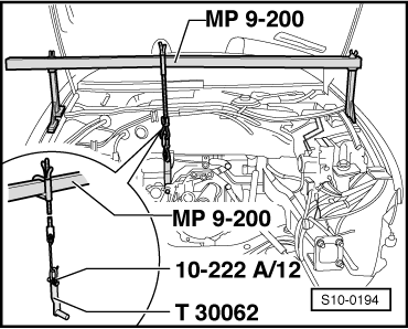
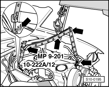
–  Observe supplementary instructions and assembly work.
–  Remove the starter → Electrical System; Rep. Gr.27.
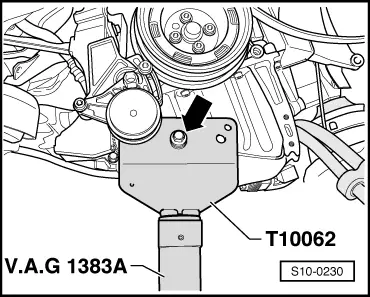
–  Release engine/gearbox connecting screws at the top.
  Note
Just loosen a connecting screw, that is do not screw it right out.
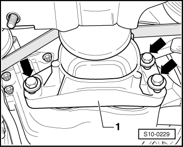
–  Unscrew the top fixing nuts for the engine mounting on the right and left.
   
–  Unbolt the dead stop -1--arrows-.
  S10-0229
–  Screw the adjusted mount -T10062- with original screw and original washer (4 mm thick) through the bore in the middle -arrow- onto the oil pan on the right and tighten up the bolted connection to 30 Nm.
–  Lift up the engine and gearbox with installed mount -T10062- and engine/gearbox lifter -V.A.G 1383 A- sufficiently in order to be able to remove the connecting screws on the engine/gearbox from below.
–  Remove the connecting screws on the engine/gearbox at bottom and lower the assembly again.
  S10-0230
–  Install supporting device -MP9-200 (10-222A)- with its additional hooks -10-222A/12- as shown in figure.
–  Hook the mount -T30062 (3147)- into the screw hole of the gearbox bell (shown in the figure on removed engine).
  S10-0194
–  Hook on the suspension fixture -MP9-201 (2024 A)- as follows and raise slightly with the workshop crane -V.A.G 1202 A -.
On the belt pulley side: 5th hole of the extension - 10-222A/12 - in Position 1.
On the flywheel side: 3rd hole of vertical perforated bar in position 8.
  WARNING
Use securing pins on the hooks and rig pins to prevent release.
  Note
t  The rig positions on the supporting bracket marked 1...8 are pointed from the belt pulley to the flywheel.
t  The holes in the perforated bars and extension are counted from the hook.
–  Remove the upper engine/gearbox connecting screws.
–  Lift out engine toward front.
  Note
Engine and gearbox must be guided carefully when lifted out, in order to avoid damage.
Secure the engine with bushings -T30010- and gearbox mount -MP 1-202 - and on the assembly stand -MP 9-101- before performing assembly work.
  S10-0195

Enginecrankshaft group, pistons > < Handling the ceramic pencil type glow plugs