
Superb
| Disassembling and assembling piston and conrod |

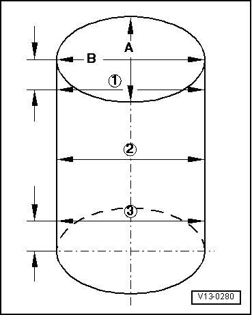
| 1 - | Piston rings |
| q | Offset joint 120 ° |
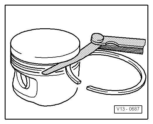
| q | use piston ring pliers for removing and installing |
| q | marking “TOP” faces piston crown |
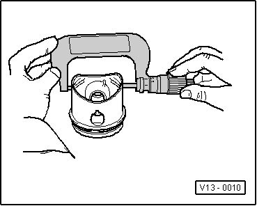
| q | inspect gap clearance → Fig. |
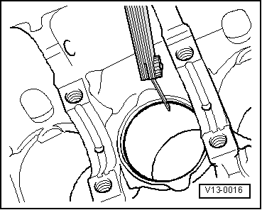
| q | inspect end clearance → Fig. |
| q | oil scraper ring, 2-part or 3-part, mixed lining is admissible |
| 2 - | Piston |
| q | check → Fig. |
| q | mark installation position and matching cylinder |
| q | arrow on piston crown faces towards the belt pulley side |
| q | use piston ring tensioning strap for installing |
| q | piston Ø 80.965 mm |
| 3 - | Piston pin |
| q | if stiff, heat piston to 60°C |
| q | with drift -MP 3-400- removing and installing |
| 4 - | Circlip |
| 5 - | Conrod |
| q | with a split bearing cap |
| q | replace as a set only |
| q | mark assignment to cylinder -B- |
| q | Fitting position: markings -A- point toward belt pulley side |
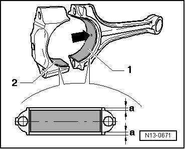
| 6 - | Bearing shell |
| q | check fitting position → Fig. |
| q | do not mix up used bearing shells |
| q | Axial play when new: 0.05...0.31 mm, wear limit: 0.37 mm |
| 7 - | Cylinder block |
| q | inspect cylinder bore → Fig. |
| q | piston Ø 81.01 mm |
| 8 - | Conrod cap |
| q | Check fitting position |
| q | One result of the conrod being separated in the cracking process is that the cover only fits in one position and only to the relevant conrod |
| 9 - | Oil injection nozzle |
| q | For piston cooling |
| 10 - | Pressure relief valve, 27 Nm |
| q | Opening pressure: test pressure 0.13...0.16 MPa (1.3...1.6 bar) positive pressure |
| 11 - | Conrod bolt, 30 Nm + torque a further +90 ° (1/4 turn) |
| q | replace |
| q | oil thread and head contact surface |
|
|
|
| Piston ring | Gap clearance | ||
| new | Wear limit | ||
| Compression rings | mm | 0,20...0,40 | 0,8 |
| Oil scraper ring | mm | 0,25...0,50 | 0,8 |
|
|
| Piston ring | End clearance | ||
| new | Wear limit | ||
| Compression rings | mm | 0,06...0,09 | 0,20 |
| Oil scraper ring | mm | 0,03...0,06 | 0,15 |
|
|
 Note
Note
|
|