
Superb
| Disassembling and assembling pistons and conrods |

| 1 - | Piston rings |
| q | Offset joint 120° |
| q | use piston ring pliers for removing and installing |
| q | Marking “TOP” faces up |
| q | Inspect gap clearance → Fig. |
| q | inspect play in the slot → Fig. |
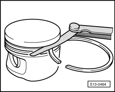
| 2 - | Piston |
| q | with combustion chamber |
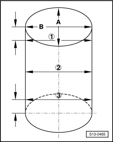
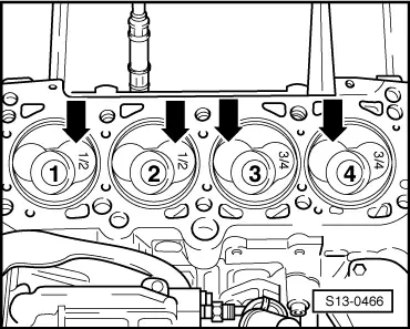
| q | mark installation position and matching cylinder |
| q | installation position and matching cylinder → Fig. |
| q | arrow on piston crown faces towards the belt pulley |
| q | use piston ring tensioning strap for installing |
| q | replace if cracks present |
| q | Check piston projection at top dead centre → Chapter |
| q | Piston dimension: Ø 80.96mm |
| 3 - | Piston pin |
| q | if stiff, heat piston to approx. 60°C |
| 4 - | Circlip |
| 5 - | Conrod |
| q | with a split cover |
| q | There must be no dirt or burrs on fracture surfaces |
| q | separate new conrod → Chapter |
| q | Pay attention to the part number |
| q | always replace as a set only |
| q | pay attention to correct installation position |
| q | mark matching cylinder -A- |
| q | Fitting position: Markings -B- point towards the belt pulley |
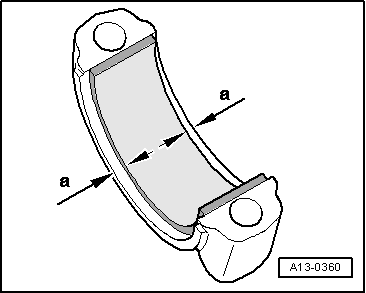
| 6 - | Bearing shell |
| q | Observe version: top bearing shell (towards the piston) must be made from a long lasting material |
| q | Distinguishing feature: black marking on the contact surface near the separation point |
| q | do not mix up used bearing shells |
| q | Insert bearing shells in the centre → Fig. |
| q | check for firm seating |
| q | Axial clearance: Wear limit 0.37 mm |
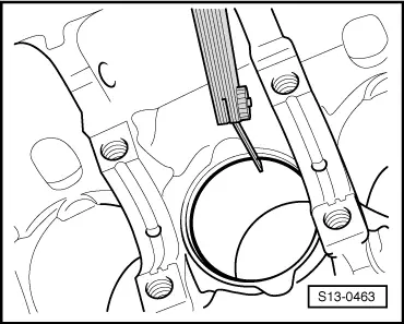
| 7 - | Cylinder block |
| q | inspect cylinder bore → Fig. |
| q | Cylinder dimension: Ø 81.01 mm |
| 8 - | Conrod bearing cap |
| q | cracked cover fits only in one position at the relevant conrod |
| q | There must be no dirt or burrs on fracture surfaces |
| q | pay attention to correct installation position |
| q | mark matching cylinder -A- |
| q | Fitting position: Markings -B- point towards the belt pulley |
| 9 - | Oil injection nozzle |
| q | for piston cooling |
| 10 - | 25 Nm |
| q | replace without sealant |
| 11 - | Conrod bolt, 30 Nm + torque a further + 90° (1/4 turn) |
| q | replace |
| q | Oil thread and contact surface |
|
|
|
|
| Piston ring | New mm | Wear limit mm |
| 1. Compression ring | 0,20...0,40 | 1,0 |
| 2. Compression ring | 0,20...0,40 | 1,0 |
| Oil scraper ring | 0,25...0,50 | 1,0 |
|
|
| Piston ring | New mm | Wear limit mm |
| 1. Compression ring | 0,06...0,09 | 0,25 |
| 2. Compression ring | 0,05...0,08 | 0,25 |
| Oil scraper ring | 0,03...0,06 | 0,15 |
 Note
Note
|
|