
Superb
 Note
Note
|

| 1 - | Gearbox housing |
| q | is made out of aluminium or magnesium → Chapter |
| q | assign → Electronic Catalogue of Original Parts |
| 2 - | Adjusting washer S2 |
| q | Note thickness |
| q | Setting overview → Chapter |
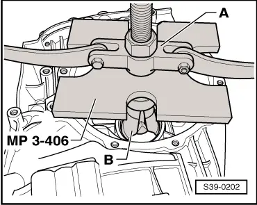
| 3 - | Right outer ring/tapered-roller bearing |
| q | removing → Fig. |
| q | installing → Fig. |
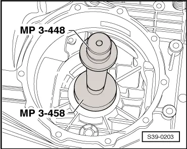
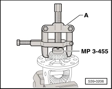
| 4 - | Right inner ring/tapered-roller bearing |
| q | remove → Fig. |
| q | pressing on → Fig. |
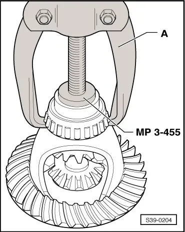
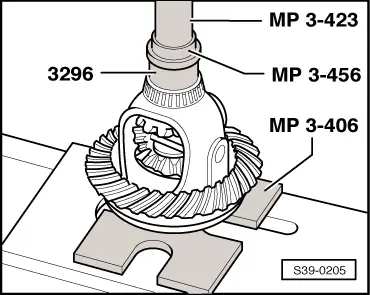
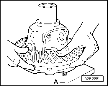
| 5 - | Crown wheel |
| q | paired with secondary shaft (drive train) |
| q | Assign the components by gearbox code letters → Chapter via the → electronic catalogue of original parts. |
| q | drive out with drift pin → Fig. |
| q | mounting on differential housing → Fig. |
| 6 - | Differential housing |
| q | left bearing assembly modified as of 05.03 |
| q | Assign the components by gearbox code letters → Chapter via the → electronic catalogue of original parts. |
| 7 - | 60 Nm and torque a further 45° |
| q | always replace → Electronic Catalogue of Original Parts |
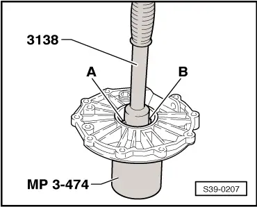
| 8 - | Left inner ring/tapered-roller bearing |
| q | remove → Fig. |
| q | pressing on → Fig. |
Note| As of 05.03 the differential housing of the bearing assembly for the left tapered-roller bearing was provided with a large radius at the inner stop. The left inner ring/tapered-roller bearing was adapted equivalently. Tapered-roller bearings of old fitting status must no longer be mounted in the new differential housings. |
| q | assign → Electronic Catalogue of Original Parts |
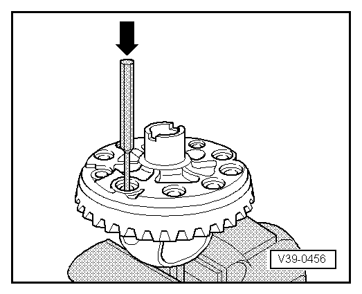
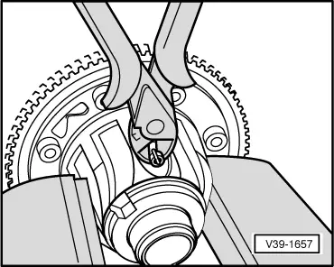
| 9 - | Drive wheel for speedometer |
| q | removing and installing → Chapter |
| q | the drive gear must be carefully installed and without tilting onto the differential gear |
| q | do not excert any force otherwise the drive wheel can break |
| q | as of 06.03 is no longer fitted on vehicles with ABS |
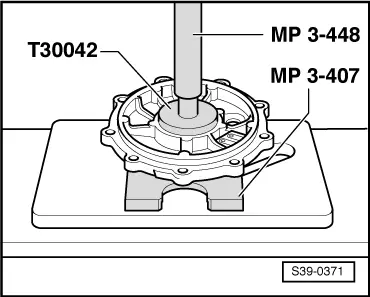
| 10 - | Left outer ring/tapered-roller bearing |
| q | left tapered-roller bearing modified as of 05.03 |
| q | Assign the components by gearbox code letters → Chapter via the → electronic catalogue of original parts. |
| q | extracting → Fig. |
| q | installing → Fig. |
| 11 - | Adjusting washer S1 |
| q | Note thickness |
| q | Setting overview → Chapter |
| 12 - | Cover |
| q | for final drive |
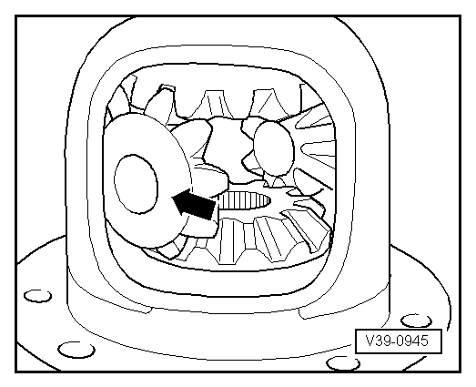
| 13 - | Differential bevel gear large |
| q | installing → Fig. |
| 14 - | Differential bevel gear shaft |
| q | drive out with drift |
| 15 - | Tensioning sleeve |
| q | to secure the differential bevel gear shaft |
| q | removing and installing tensioning sleeve → Fig. |
| 16 - | Differential bevel gear small |
| q | installing → Fig. |
| 17 - | Stop disc compound |
| q | insert with gear oil |
|
|
Note
|
|
Note
|
|
|
|
|
|
|
|
|
|
|
|
 Caution
|
|
|
|