Power transmissionRepairing the gearbox housing
| Repairing the gearbox housing |
| Special tools and workshop equipment required |
| t
| Drive bushing -MP1-316 (30-100)- |
| t
| Drift -MP3-403 (VW 295)- |
| t
| Adapter -MP3-403/1 (VW 295A)- |
| t
| Multi-purpose tool -MP3-419 (VW 771)- |
| t
| Pipe section -MP3-479 (VW 423)- |
| t
| Insertion tube -MP3-485 (32-109)- |
| t
| Assembly device -MP6-414 (3253)- |
| t
| Retaining plate -T30027 (VW 801)- |
| t
| Locking pin -T30044 (2064)- |
| t
| Guide bolt -T30074 (10-15)- |
| t
| Interior extractor -3275- |
| t
| Interior extractor 14.5...18.5 mm, e.g. -Kukko 21/2- |
| t
| Countersupport, e.g. -Kukko 22/1- |
| t
| Countersupport, e.g. -Kukko 22/2- |
|
|
|

Note
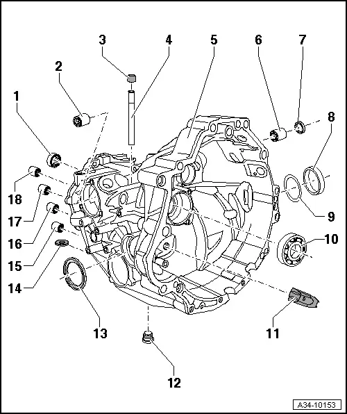
| On certain gearboxes, bushings for shift rods are installed instead of ball sleeves Pos. 15 to 18. Remove these bushings → Fig.. Drive in bushings with locking pin -T30044 (2064)- up to the stop. The gearbox housing was modified in combination with the bushings. Assign components via the → Electronic catalogue of original parts. |
|
q
| measuring insertion depth → Fig.. |
|
q
| after installing, secure by caulking → Fig. |
|
q
| driving in and securing → Fig. |
|
q
| clip on cap Pos. 3 for gearbox bleeder |
|
q
| if replaced: Deterime positioning for 2nd gear sliding gear again → Chapter, setting secondary shaft and differential (drive chain) → Chapter |
| 7 - | Gasket for gearshift shaft |
|
q
| can be replaced if removing (not disassembling) the gearbox → Chapter |
|
q
| only mount with assembling sleeve on fitted gearshift shaft → Chapter |
| 8 - | Right outer ring/tapered-roller bearing |
|
q
| if replaced: Adjusting the differential gear (crown wheel) → Chapter |
| 9 - | Adjusting washer “S2” |
| 10 - | Grooved ball bearing |
|
q
| remove with gearbox disassembled → Fig. |
|
q
| remove with gearbox removed (not disassembled) → Chapter |
| 12 - | Oil drain plug - 40 Nm |
|
q
| insert into housing rib |
|
q
| for reverse gear shift rod |
|
q
| measuring insertion depth → Fig.. |
|
q
| Change: on certain gearboxes a bushing is fitted instead of the ball sleeve |
|
q
| for 1st and 2nd gear shift rod |
|
q
| measuring insertion depth → Fig.. |
|
q
| Change: on certain gearboxes a bushing is fitted instead of the ball sleeve |
|
q
| for 3rd and 4th gear shift rod |
|
q
| measuring insertion depth → Fig.. |
|
q
| Change: on certain gearboxes a bushing is fitted instead of the ball sleeve |
|
q
| for 5th and 6th gear shift rod |
|
q
| measuring insertion depth → Fig.. |
|
q
| Change: on certain gearboxes a bushing is fitted instead of the ball sleeve |
| Pull needle bushing for drive shaft out of the gearbox housing |
| A - | Countersupport, e.g. -Kukko 22/2- |
| –
| If present, remove caulking recesses. |
|
|

|
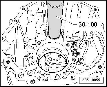
| Drive needle bushing for drive shaft into the gearbox housing |
| Position needle bushing with the lettered side (thicker end) towards the drive bushing -30-100 (MP1-316)-. |
| Insertion depth of needle bushing → Fig.. |
|
|
|
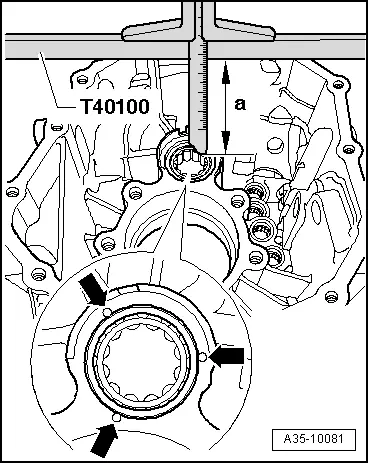
| Measure insertion depth of needle bushing and secure needle bushing by caulking |
| l
| Measurement -a- = 88.0 ± 0.5 mm |
| –
| For caulking, use a blunt centre punch with ball-shaped end (5 mmØ ball). |
| –
| The needle bushing is secured -arrows- by 3 caulking markings, offset at circumference by 120°. |
|
|
|
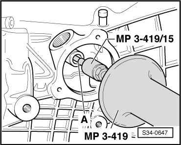
| Pull out ball sleeve for gearshift shaft |
| A - | Interior extractor 14.5...18.5 mm, e.g. -Kukko 21/2- |
| –
| If present, remove caulking recesses. |
|
|
|
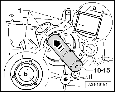
| Drive in ball sleeve for gearshfit shaft and secure by caulking |
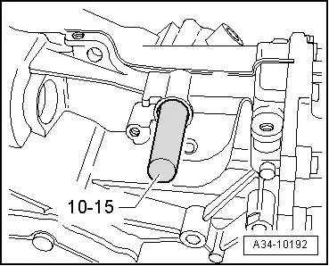
| Position ball sleeve with the lettered side (thicker end) towards guide bolt -10-15 (T30074)-. |
| –
| Drive in ball sleeve -1- to the fitting dimension -a- = 1.5 ± 0.5 mm under housing surface. |
| After driving in, secure ball sleeve by caulking as follows: |
| –
| For caulking, use a blunt centre punch with ball-shaped end. |
| –
| Ball sleeve is secured by 3 caulking markings -b-, offset at circumference by 120°. |
|
|
|
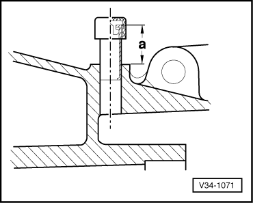
| Fitting dimension of ventilation pipe |
|
|
|
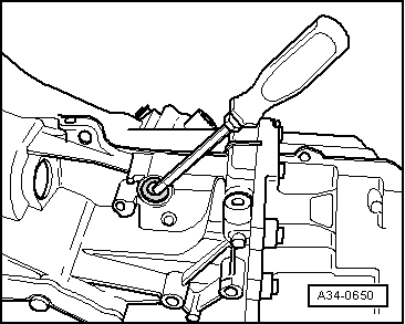
| Pulling out gasket ring for gearshift shaft with gearbox disassembled |
| –
| Carefully lever out gasket ring with a screwdriver. |
|
|
|
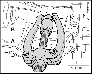
| Pull out ball sleeve for gearshift shaft |
| First remove gasket ring for gearshift shaft → Fig.. |
| A - | Countersupport, e.g. -Kukko 22/1- |
| B - | Interior extractor 14.5...18.5 mm, e.g. -Kukko 21/2- |
|
|
|
| Drive in ball sleeve for gearshift shaft |
| l
| Insertion depth: 8.5 ± 0.5 mm under housing surface. |
|
|
|
| Driving in gasket ring for gearshift shaft |
| –
| Fill half the space between the sealing lip and dust lip with sealing grease -G 052 128 A1-. |
| –
| Lightly lubricate the outer circumference of the gasket ring. |
| –
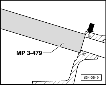
| Driving in gasket ring -arrow- up to 1.0 ± 0.2 mm under housing surface, at the same time do not tilt. |
|
|
|
| Removing grooved ball bearing for drive shaft with gearbox disassembled |
| –
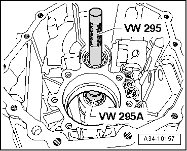
| Position adapter -VW 295A (MP3-403/1)- with small Ø into the grooved ball bearing. |
| –
| Drive out grooved ball bearing. |
|
|
|
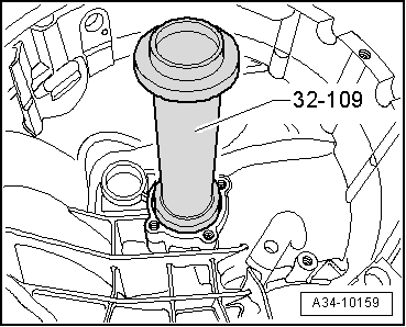
| Drive in grooved ball bearing for drive shaft up to the stop. |
| The closed side of the cage for the balls points to the gearbox housing. |
| –
| Drive grooved ball bearing up to the stop into the gearbox housing. |
|
|
|
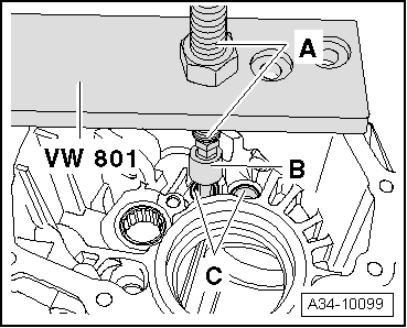
| Pull out ball sleeve or bushing -C- for shift rod. |
| A - | Countersupport, e.g. -Kukko 22/2- |
| B - | Interior extractor 14.5...18.5 mm, e.g. -Kukko 21/2- |
|
|
|
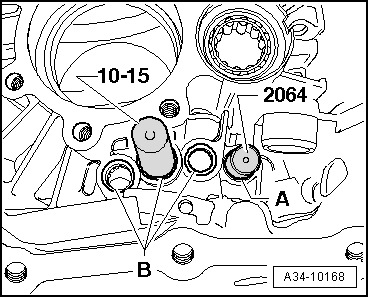
| Drive in ball sleeve for shift rod |
| –
| Drive in ball sleeve -A- for 5th/6th gear shift rod with locking pin -2064 (T30044)- to the fitting dimension → Fig.. |
| –
| Drive in the remaining 3 ball sleeves -B- with guide bolt -10-15 (T30074)- to the fitting dimension → Fig.. |
| Position ball sleeve with the lettered side (thicker end) towards guide bolt -10-15 (T30074)- or locking pin -2064 (T30044)-. |
|
|
|
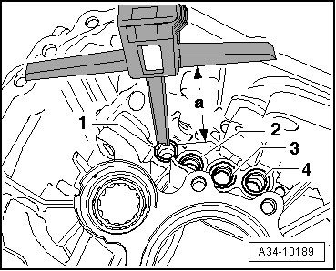
| Insertion depth of ball sleeves in gearbox housing |
| –
| Press in ball sleeve for 5th/6th gear shift rod -1- to the dimension -a- = 143.5 ± 0.5 mm. |
| –
| Press in ball sleeve for 3rd/4th gear shift rod -2- to the dimension -a- = 133.5 ± 0.5 mm. |
| –
| Press in ball sleeve for 1st/2nd gear shift rod -3- to the dimension -a- = 116.5 ± 0.5 mm. |
| –
| Press in ball sleeve for reverse gear shift rod -4- to the dimension -a- = 116.5 ± 0.5 mm. |
Note | Measure from the housing contact surface to the respective ball sleeve with a depth gauge. |
|
|
|
06 Transmission