skoda Workshop Repair Guides

Skoda Yeti Workshop Service and Repair Manuals

Hydraulic Control Unit, Brake Servo Unit/Master Brake Cylinder ABS Mark 70 (ABS/TCS) > < Connecting brake lines from the master brake cylinder to the hydraulic unit - Vehicles with right-hand drive
Removing and installing control unit and hydraulic unit - Vehicles with right-hand drive
Special tools and workshop equipment required
t  Brake pedal load e.g. -V.A.G 1869/2-
t  Plugs from repair kit -1H0 698 311 A-
Removing:
Fitting location:
The ABS control unit is located on the left in the engine compartment.
  WARNING
The brake lines around the hydraulic unit must not be bent!
–  Read out and note the actual control unit coding → Vehicle diagnostic tester.
–  Remove engine cover.
–  Remove battery → Electrical System; Rep. gr.27.
–  Remove induction pipe and air filter → Engine; Rep. gr.23 or → Engine; Rep. gr.24.
–  Remove battery tray → Electrical System; Rep. gr.27.
–  Position brake pedal load e.g. -V.A.G 1869/2-.
–  Attach the bleeder hose of the bleeding bottle onto the bleeder screws of the front left and rear left brake caliper and open the bleeder screws.
–  Press down brake pedal with brake pedal load e.g. -V.A.G 1869/2- at least 60 mm.
–  Close front left and rear left bleeder screws.
  Note
Do not remove brake pedal load, e.g. -V.A.G 1869/2-.
–  Place sufficient non-fluffing cloths under the control unit and the hydraulic unit.
–  Extract as much brake fluid as possible from the brake fluid reservoir.
Make sure that no brake fluid gets onto the contacts of the plug connections.
   
–  Mark both brake lines from the master brake cylinder -A- and -B- and unscrew from the hydraulic unit.
–  Close the brake lines and threaded holes immediately with plugs from the repair kit -1H0 698 311 A-.
–  Mark the brake lines (for brake calipers) -1- to -4-, unscrew and close with plugs from the repair kit -1H0 698 311 A-.
  N45-10171
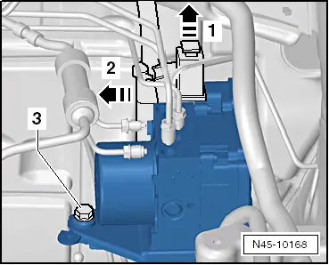
–  Release the plug at the ABS control unit -in direction of arrow 1-.
–  Disconnect the plug from the control unit in -direction of arrow 2-.
–  Release screw -3-.
–  Pull the ABS control unit with bracket out of the rubber bearings in the console in -direction of arrow 2-.
–  Remove the ABS control unit and unscrew the bracket from the ABS control unit.
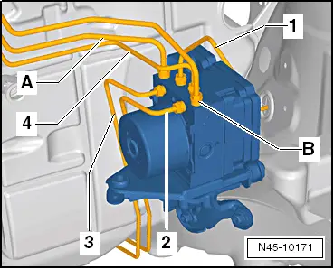
  Note
If the rubber bearings are pulled out of the console at the same time, place the bearings in the same position again → Item.
Installing:
  Note
t  Only then remove plugs from the new hydraulic unit when the relevant brake line is installed.
t  If the plugs were already removed from the hydraulic unit before the brake line is installed, then brake fluid may escape and adequate filling and bleeding can no longer be guaranteed.
–  Screw the bracket for the ABS control unit onto the ABS control unit and tighten to the recommended tightening torque.
–  Moisten the bolt of the support → Item with lubricant, e.g. -D 007 000 A2-, before inserting into the rubber bearings.
–  Insert the ABS hydraulic unit with bracket into the rubber bearings of the console.
  WARNING
Make sure that the rubber bearings are not pressed out of the console when installing the bracket. After installing, check the ABS control unit for tight fit, otherwise failure may be caused by a malfunctioning.
  N45-10168
–  Screw in screw -3- and tighten to the recommended tightening torque.
–  Connect the plug to the control unit against the -direction of arrow 2- and lock.
–  Remove the plugs consecutively from the brake lines and the ABS control unit.
–  Screw the marked brake lines onto the ABS control unit.
–  Install battery tray → Electrical System; Rep. gr.27.
–  Install induction pipe and air filter → Engine; Rep. gr.23 or → Engine; Rep. gr.24.
–  Install battery → Electrical System; Rep. gr.27.
  Note
If the battery earth strap is disconnected and connected, carry out certain additional operations → Electrical System; Rep. gr.27.
–  Position engine cover.
–  Remove brake pedal load e.g. -V.A.G 1869/2-.
–  Bleeding brake system → Chapter.
–  Code the control unit -J104- → Vehicle diagnostic tester.
While doing so, a basic setting of the steering angle sender -G85-, the lateral acceleration sender -G200-, the brake pressure sender 1 -G201- and the longitudinal acceleration sender -G251- must be performed → Vehicle diagnostic tester.
  N45-10168
Tightening torques: 
Bracket to ABS control unit8 Nm
Screw for bracket to console8 Nm
Brake lines to ABS unit: 
Thread M 10 x 114 Nm
Thread M 12 × 114 Nm


Hydraulic Control Unit, Brake Servo Unit/Master Brake Cylinder ABS Mark 70 (ABS/TCS) > < Connecting brake lines from the master brake cylinder to the hydraulic unit - Vehicles with right-hand drive