
Yeti
| Electric/electronic components and fitting locations for the automatic gearbox DSG - 02E |
| Vehicles Octavia II |
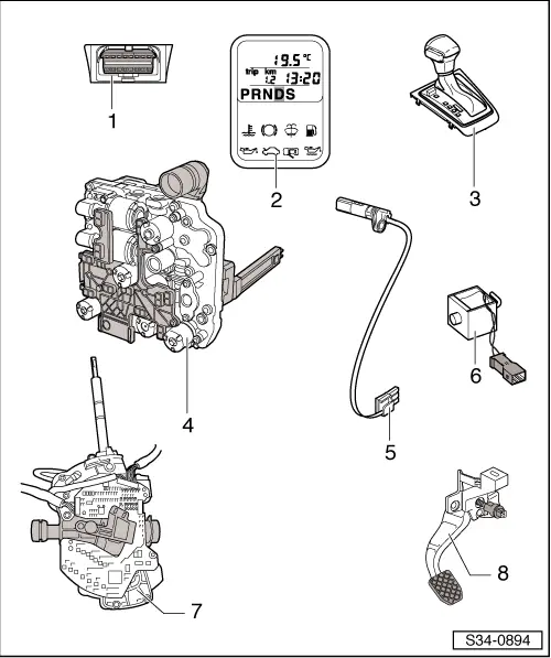
| 1 - | Diagnostic connection |
| q | Fitting location: Cover in driver's footwell |
| 2 - | Selector lever position indicator -Y6- |
| q | Fitting location: integrated in the dash panel insert |
| q | a switched off gear display points to an emergency operation with deactivated gearbox control unit |
| q | a fully lit gear display points to an emergency operation with activated gearbox control unit |
| q | can only be replaced together with the dash panel insert → Electrical System; Rep. gr.90 |
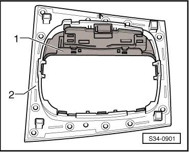
| 3 - | Cover for shift mechanism with lamp for selector lever scale illumination -L101- |
| q | the lamp for selector lever scale illumination -L101- is integrated in the cover frame; fitting location → Fig. |
| q | the lamp for selector lever scale illumination -L101- is checked by self-diagnosis |
| q | removing and installing → Chapter |
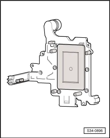
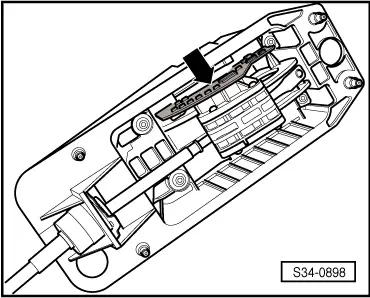
| 4 - | Mechatronics for double clutch gearbox -J743- |
| q | Fitting location → Fig. |
| q | is checked by self-diagnosis |
| q | removing and installing → Chapter |
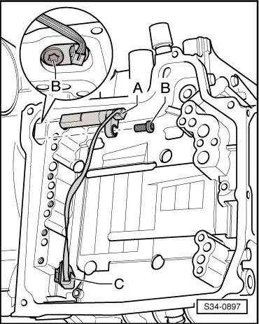
| 5 - | Gearbox input r.p.m. sender -G182- and temperature sender for clutch -G509- |
| q | Fitting location → Fig. |
| q | is checked by self-diagnosis |
| q | before the sender can be removed, the mechatronics for double clutch gearbox -J743- must be removed → Chapter |
| q | removing and installing → Chapter |
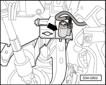
| 6 - | Selector lever lock solenoid -N110- |
| q | Fitting location → Fig. |
| q | is checked by self-diagnosis |
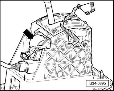
| 7 - | Selector lever -E313- with Tiptronic switch -F189-, selector lever sensor control unit -J587- and selector lever switch locked in P -F319- |
| q | Fitting location → Fig. |
| q | are checked by self-diagnosis |
| q | Tiptronic switch -F189-, selector lever sensor control unit -J587- and selector lever switch locked in P -F319- are integrated into the shift mechanism. |
| q | these components cannot be replaced separately; the removal and installation procedure is only possible together with the gearshift mechanism → Chapter |
| 8 - | Brake light switch -F- |
| q | Fitting location up to 10.05 → Fig. |
| q | Fitting location as of 11.05 → Fig. |
| q | Signal transfer from engine to gearbox control unit via CAN databus |
| q | is checked by self-diagnosis |
| q | removing and installing → Chassis; Rep. gr.46 |
| Vehicles Superb II |
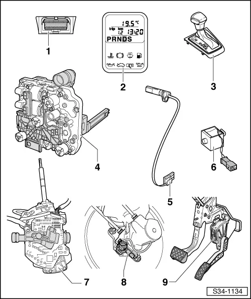
| 1 - | Diagnostic connection |
| q | Fitting location: Cover in driver's footwell |
| 2 - | Selector lever position indicator -Y6- |
| q | Fitting location: integrated in the dash panel insert |
| q | a switched off gear display points to an emergency operation with deactivated gearbox control unit |
| q | a fully lit gear display points to an emergency operation with activated gearbox control unit |
| q | can only be replaced together with the dash panel insert → Electrical System; Rep. gr.90 |
| 3 - | Cover for shift mechanism with lamp for selector lever scale illumination -L101- |
| q | the lamp for selector lever scale illumination -L101- is integrated in the cover frame; fitting location → Fig. |
| q | the lamp for selector lever scale illumination -L101- is checked by self-diagnosis |
| q | removing and installing → Chapter |
| 4 - | Mechatronics for double clutch gearbox -J743- |
| q | Fitting location → Fig. |
| q | is checked by self-diagnosis |
| q | removing and installing → Chapter |
| 5 - | Gearbox input r.p.m. sender -G182- and temperature sender for clutch -G509- |
| q | Fitting location → Fig. |
| q | is checked by self-diagnosis |
| q | before the sender can be removed, the mechatronics for double clutch gearbox -J743- must be removed → Chapter |
| q | removing and installing → Chapter |
| 6 - | Selector lever lock solenoid -N110- |
| q | Fitting location → Fig. |
| q | is checked by self-diagnosis |
| 7 - | Selector lever -E313- with Tiptronic switch -F189-, selector lever sensor control unit -J587- and selector lever switch locked in P -F319- |
| q | Fitting location → Fig. |
| q | are checked by self-diagnosis |
| q | Tiptronic switch -F189-, selector lever sensor control unit -J587- and selector lever switch locked in P -F319- are integrated into the shift mechanism. |
| q | these components cannot be replaced separately; the removal and installation procedure is only possible together with the gearshift mechanism → Chapter |
| 8 - | Brake light switch -F- and brake pedal switch -F47- |
| q | Fitting location → Fig. |
| q | Signal transfer from engine to gearbox control unit via CAN databus |
| q | is checked by self-diagnosis |
| q | removing and installing → Chassis; Rep. gr.46 |
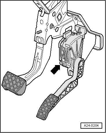
| 9 - | Kick-down switch -F8- |
| q | Fitting location → Fig. |
| q | Signal transfer from engine to gearbox control unit via CAN databus |
| q | is checked by self-diagnosis |
| q | Removing and Installing → Engine; Rep. gr.20 |
| Vehicles Yeti |
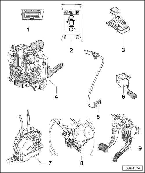
| 1 - | Diagnostic connection |
| q | Fitting location: Cover in driver's footwell |
| 2 - | Selector lever position indicator -Y6- |
| q | Fitting location: integrated in the dash panel insert |
| q | a switched off gear display points to an emergency operation with deactivated gearbox control unit |
| q | a fully lit gear display points to an emergency operation with activated gearbox control unit |
| q | can only be replaced together with the dash panel insert → Electrical System; Rep. gr.90 |
| 3 - | Cover for shift mechanism with lamp for selector lever scale illumination -L101- |
| q | the lamp for selector lever scale illumination -L101- is integrated in the cover frame; fitting location → Fig. |
| q | the lamp for selector lever scale illumination -L101- is checked by self-diagnosis |
| q | removing and installing → Chapter |
| 4 - | Mechatronics for double clutch gearbox -J743- |
| q | Fitting location → Fig. |
| q | is checked by self-diagnosis |
| q | removing and installing → Chapter |
| 5 - | Gearbox input r.p.m. sender -G182- and temperature sender for clutch -G509- |
| q | Fitting location → Fig. |
| q | is checked by self-diagnosis |
| q | before the sender can be removed, the mechatronics for double clutch gearbox -J743- must be removed → Chapter |
| q | removing and installing → Chapter |
| 6 - | Selector lever lock solenoid -N110- |
| q | Fitting location: is integrated firmly in the gearshift mechanism and cannot be replaced separately |
| q | is checked by self-diagnosis |
| q | the removal and installation procedure is only possible together with the gearshift mechanism → Chapter. |
| 7 - | Selector lever -E313- with Tiptronic switch -F189-, selector lever sensor control unit -J587- and selector lever switch locked in P -F319- |
| q | are checked by self-diagnosis |
| q | Tiptronic switch -F189-, selector lever sensor control unit -J587- and selector lever switch locked in P -F319- are integrated into the shift mechanism. |
| q | these components cannot be replaced separately; the removal and installation procedure is only possible together with the gearshift mechanism → Chapter |
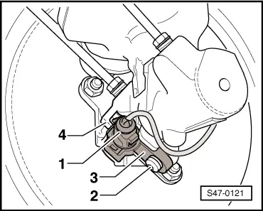
| 8 - | Brake light switch -F- and brake pedal switch -F47- |
| q | Fitting location → Fig. |
| q | Signal transfer from engine control unit to gearbox control unit via CAN databus |
| q | is checked by self-diagnosis |
| q | removing and installing → Chassis; Rep. gr.47 |
| 9 - | Kick-down switch -F8- |
| q | Fitting location → Fig. |
| q | Signal transfer from engine to gearbox control unit via CAN databus |
| q | is checked by self-diagnosis |
| q | Removing and Installing → Engine; Rep. gr.20 |
|
|
|
|
|
|
|
|
|
 Note
Note
|
|
|
|
|
|