skoda Workshop Repair Guides

Skoda Workshop Service and Repair Manuals

Tightening torques > < Removing gearbox (Yeti)
Installing gearbox (Yeti)
Installation is performed in the reverse order, pay attention to the following points:
  Note
t  Install the gearbox DSG - 02E together with the angle gearbox.
t  Replace the self-locking nuts and screws when undertaking assembly work.
t  Replace screws which have been tightened to a torquing angle as well as gasket rings and seals.
t  Secure all hose connections with hose clamps which comply with the series design → Electronic Catalogue of Original Parts.
t  All cable straps which are detached or cut open when removing, should be fitted on again in the same place when installing.
   
t  
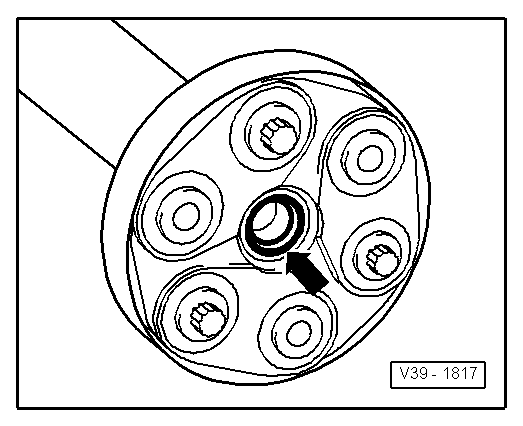
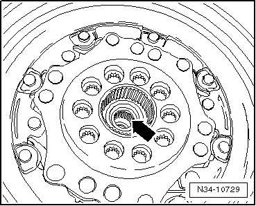
Check the needle bearing -arrow- in the crankshaft. If it is damaged or tarnished blue (caused by overheating), it must be replaced → Engine; Rep. gr.13.
t  Lightly grease the needle bearing -arrow- and the drive shaft pin (not the serration) with high-temperature grease -G 052 133 A2-.
t  
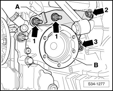
Check whether the dowel sleeves for centering the engine/gearbox are present in the cylinder block; insert if necessary.
t  If the gearbox is inserted, ensure the intermediate plate between the engine and gearbox is correctly installed.
  N34-10729
–  Carefully raise gearbox with the engine/gearbox jack -V.A.G 1383 A- and put in its installation position with the gearbox mount -3282-.
l  The gearbox is pulled off from the engine by approx. 30 mm.
  S34-1173
–  Screw the gearbox carrier -A- to the engine by hand before inserting the gearbox -arrows-.
–  Do not get the cables trapped when inserting the gearbox.
–  Screw on the gearbox to the engine → Chapter.
–  Attach the selector lever control cable to the gearbox.
  Note
Do not bend or buckle selector lever control cable.
  S34-1273
Install the unit mounting as follows:
–  Insert the gearbox console -A- between the gearbox and the supporting arm of the gearbox mount.
–  Also lift the gearbox with the spindles of the supporting device to the supporting arm of the gearbox mount at the same time.
–  Tighten the gearbox console -A- with new screws -1- at the gearbox.
–  First of all tighten the screws -2- only by hand.
  Caution
Before screwing in the screws -2- the gearbox console and the supporting arm of the gearbox mount must be absolutely parallel to one another, otherwise the thread is damaged.
–  Remove the gearbox mount -3282- from the gearbox.
  S34-0946
–  Screw the gearbox mount -A- to the angle gearbox by hand -arrow 1-.
–  Then tighten the screws -arrows 1 … 3- to the recommended tightening torque, while doing so observe the tightening order → Chapter.
–  Attach the left and right drive shaft to the flange shafts of the gearbox → Chassis; Rep. gr.40.
  S34-1277
–  Install heat shield for right drive shaft at the angle gearbox -arrows-.
Vehicles with diesel particle filter
–  Install particle filter with bracket for particle filter → Engine; Rep. gr.26.
Continued for all vehicles
–  Install the assembly carrier → Chassis; Rep. gr.40.
–  Press the engine/gearbox unit towards the bulkhead plenum chamber; at the same time the stud of the output flange of the angle gearbox must be carefully inserted into the flange of the propshaft.
  Note
  N34-11224
t  The gasket rings -arrow- in the flanges of the propshaft must not be damaged when removing and installing. In case of damaged gasket rings the propshaft must be replaced.
t  Slide the propshaft horizontally onto the stud of the angle gearbox.
  V39-1817
–  Screw the pendulum support with new screws -arrows- onto the gearbox → Engine; Rep. gr.10.
–  Screw propshaft onto the flange of the angle gearbox → Chapter.
–  Installing starter and cable → Electrical System; Rep. gr.27.
  S34-0944
–  Mount the plug -A- of the mechatronics as follows:
l  The arrows -D- on the mechatronics -B- and on the plug -A- as well as the peg -C- must be on the same line and point upwards.
l  Then mount the plug -A- carefully up to the stop and lock the cap by turning it to the right in -direction of arrow-.
–  Assemble exhaust system free of stress and install bracket for the exhaust system at the assembly carrier → Engine; Rep. gr.26.
  S34-1174
–  Install fan shroud -arrow- with fans → Engine; Rep. gr.19.
–  Install left and right charge air hose → Engine; Rep. gr.21.
–  Check the adjustment of the engine and gearbox mounting and tighten the screws of the gearbox mount to the gearbox console → Engine; Rep. gr.10.
–  Install the battery tray and battery → Electrical System; Rep. gr.27.
–  Inspect setting of selector lever control cable and adjust if necessary → Chapter.
–  Install air filter → Engine; Rep. gr.23.
–  Inspect coolant level in the cooling system, top up if necessary → Engine; Rep. gr.19.
–  Inspect gear oil level and top up if necessary → Chapter.
–  Install sound dampening → Body Work; Rep. gr.50 and install front left and right wheelhouse liner → Body Work; Rep. gr.66.
–  Install front wheel → Chassis; Rep. gr.44.
  Note
If the battery earth strap is disconnected and connected, carry out certain additional operations → Electrical System; Rep. gr.27.
  N34-11165

Tightening torques > < Removing gearbox (Yeti)