
Yeti
 Note
Note| t | When installing new pinions or a new output shaft observe the technical data → Chapter. |
| t | Insert all bearings, sliding gears and synchronizer rings onto the output shaft with gear oil. |
| t | Do not interchange the synchronizer rings, if re-used always assign to the original sliding gear. |
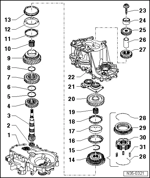
| 1 - | Clutch housing |
| q | repairing → Chapter |
| 2 - | Cylindrical-roller bearing |
| q | with circlip |
| q | removing → Fig. |
| q | installing → Fig. |
| q | Fitting position: the circlip in the bearing points towards the output shaft |
| 3 - | Output shaft |
| q | if an inner ring is fitted as a bearing assembly for the cylindrical-roller bearing Pos. 2, it cannot be removed from the output shaft |
| q | Inspect bearing assembly or inner ring for cylindrical-roller bearing for scoring and damage |
| q | Replace output shaft and cylindrical-roller bearing together if there is scoring or damage on the bearing assembly or inner ring |
| 4 - | 4th gear pinion |
| q | Fitting position: the collar points to the 3rd gear → Fig. |
| q | No. of teeth → Chapter |
| 5 - | Circlip |
| 6 - | Circlip |
| 7 - | 3rd gear pinion |
| q | Fitting position: the collar points to the 4th gear → Fig. |
| q | No. of teeth → Chapter |
| 8 - | Circlip |
| 9 - | 2nd gear sliding gear |
| q | No. of teeth → Chapter |
| 10 - | Needle bearing |
| q | for 2nd gear |
| 11 - | Inner ring for 2nd gear |
| q | check for wear → Fig. |
| q | Fitting position → Fig. |
| 12 - | Outer ring for 2nd gear |
| q | place onto the inner ring Pos. 11 |
| q | replace if there are any traces of scoring or friction |
| q | Fitting position → Fig. |
| 13 - | 2nd gear synchronizer ring |
| q | check for wear → Fig. |
| q | Fitting position → Fig. |
| 14 - | Sliding sleeve with 1st and 2nd gear synchronizer body |
| q | after removing the circlip -Pos. 15- press off with the 2nd gear sliding gear → Fig. |
| q | disassembling → Fig. |
| q | Assembling sliding sleeve/synchronizer body → Fig. and → Fig. |
| q | Fitting position → Fig. |
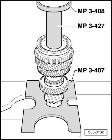
| q | pressing on → Fig. |
| 15 - | Circlip |
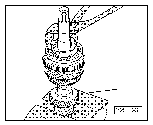
| q | pushing out → Fig. |
| q | inserting → Fig. |
| 16 - | 1st gear synchronizer ring |
| q | check for wear → Fig. |
| q | insert in such a way that the recesses lock into the arresters of the sliding sleeve Pos. 14 |
| 17 - | Outer ring for 1st gear |
| q | insert into synchronizer ring Pos. 16 |
| q | Fitting position → Fig. |
| q | replace if there are any traces of scoring or friction |
| 18 - | Inner ring for 1st gear |
| q | check for wear → Fig. |
| q | Check pegs for traces of wear |
| q | Fitting position → Fig. |
| 19 - | Needle bearing |
| q | for 1st gear |
| 20 - | 1st gear sliding gear |
| q | Fitting position → Fig. |
| q | No. of teeth → Chapter |
| 21 - | Bearing support with grooved ball bearing |
| q | Always replace grooved ball bearing together with the bearing support |
| q | If the bearing support is released from the gearbox housing, it must always be replaced → Electronic Catalogue of Original Parts |
| q | removing and installing → Chapter |
| 22 - | Gearbox housing |
| q | repairing → Chapter |
| 23 - | Screw |
| q | removing and installing → Chapter |
| 24 - | Inner ring/cylindrical-roller bearing |
| q | identify before removing |
| q | do not interchange with inner ring/cylindrical-roller bearing of input shaft |
| q | can be replaced separately |
| q | removing and installing → Chapter |
| 25 - | 6th gear pinion |
| q | Fitting position: the collar points to the bushing Pos. 26 |
| q | removing and installing → Chapter |
| q | No. of teeth → Chapter |
| 26 - | Bushing |
| q | removing and installing → Chapter |
| 27 - | 5th gear pinion |
| q | Fitting position → Chapter |
| q | press off together with bearing support Pos. 21 → Chapter |
| q | pressing on → Chapter |
| q | No. of teeth → Chapter |
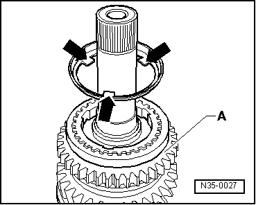
| 28 - | Spring |
| q | Fitting position → Fig. |
| 29 - | Sliding sleeve |
| 30 - | Synchronizer body |
| 31 - | Arresters (3 pieces) |
|

|
|

|
|

|
 WARNING
|

|
|

|
|

|
| Fitting dimension | Wear limit | |
| Clearance -a- | 0,75 … 1,25 mm | 0.3 mm |
|

|
| Fitting dimension | Wear limit | |
| Clearance -a- | 1,2 … 1,8 mm | 0.5 mm |
|

|
|

|
|

|
|
|
|
|
|
|
|

|
|

|