|
Main Housing, Replace (AF 20)
 Remove Remove
Remove transmission – see operation "Transmission, Remove
and Install (AF 20)". Secure converter against falling out.
|
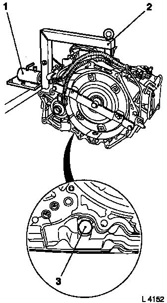
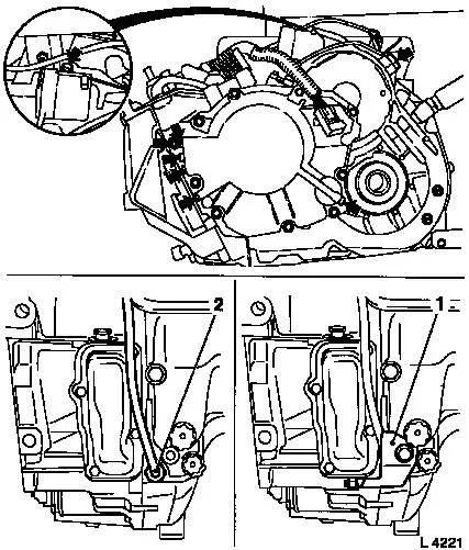
Attach transmission to KM-694-A (2). Attach assembly to KM-113-2
(1).
Remove fluid drain bolt (3), drain transmission fluid and
collect for damage diagnosis – see operation "Transmission
Fluid Condition, Check (AF 13-II/AF 17/AF 20/AF 22)".
Remove converter – see operation "Converter and/or Fluid
Pump Seal Ring, Replace (AF 13-II/AF 17/AF 20/AF 22)".
|
|
|
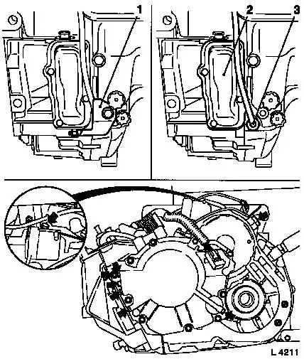
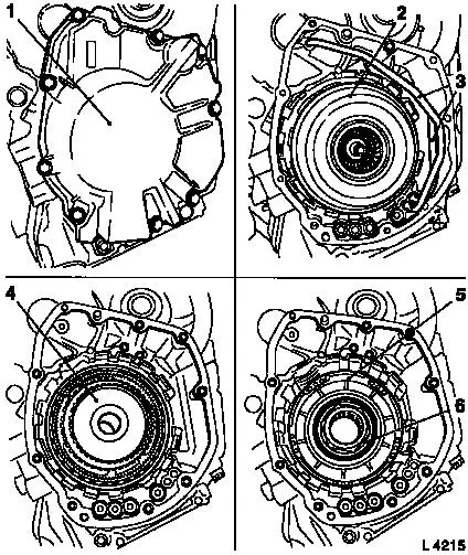
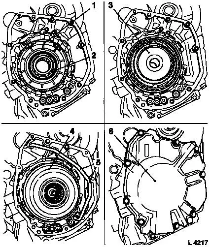
Remove cover plate (1) from side cover and transmission.
Remove fluid temperature sensor (3).
Remove auxiliary housing cover (2) from transmission.
Remove plugs (arrow). Replace seal rings of plugs.
|
|
|
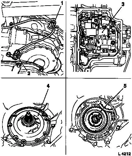
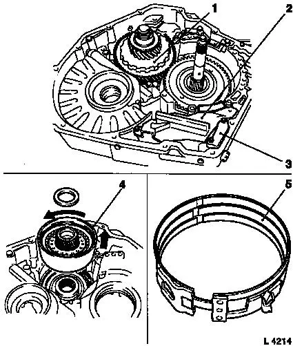
Remove transmission output speed sensor (1) and transmission
input speed sensor (2) from transmission.
Remove valve body (3) – see operation "Valve Body, Remove
and Install (Transmission Removed) (AF 20)".
Remove fluid pump assembly (4) with multi-disc brake B1 and B2
– see operation "Fluid Pump Assembly with Multi-disc Brakes
B1 and B2, Remove and Install (AF 20)".
Remove freewheel F1 (5) – see operation "Freewheel F1,
Remove and Install (AF 20)".
|
|
|
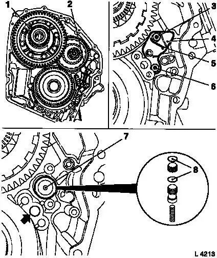
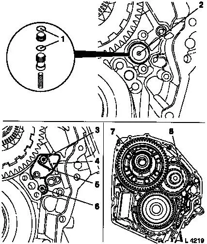
Remove differential (1) – see operation "Differential,
Remove and Install (AF 20)".
Remove parking lock (2) – see operation "Parking Lock,
Remove and Install (AF 20)".
Remove fastening bolts (3) and (6). Remove torsion spring No. 2
(5) and accumulator cover (4).
Remove accumulator piston (7) and spring – blow in
low-pressure compressed air (4 bar, arrow)
Replace O-rings (8) on cover and piston.
|
|
|
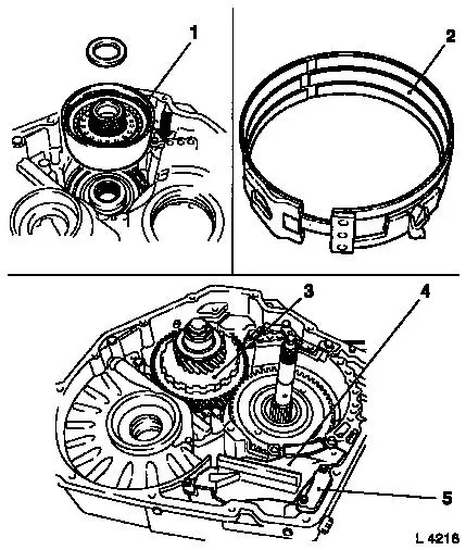
Remove main housing plate (3). Remove fluid screen (2).
Remove planetary gear set P2 (1) – see operation
"Planetary Gear Set P2, Remove and Install (AF 20)".
Remove multi-plate clutch C3 (4) and freewheel F3 with brake
band B4 (5) – see operation "Multi-plate Clutch C3 and
Freewheel F3, Remove and Install (AF 20)".
|
|
|
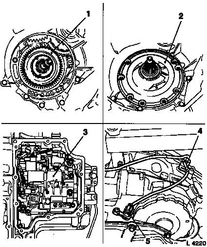
Remove rear cover (1) with piston C1 – see operation "Rear
Cover with Piston C1, Remove and Install (AF 20)".
Remove pipes (3) and drive shaft assembly (2) with multi-plate
clutch C1 and C2 – see operation "Drive Shaft Assembly with
Multi-plate Clutch C1 and C2, Remove and Install (AF 20)".
Remove planetary gear set P1 – see operation "Planetary
Gear Set P1, Remove and Install (AF 20)".
Remove piston for multi-disc brake B3 (5) and intermediate drive
gear (6) – see operation "Intermediate Drive Gear, Remove and
Install (AF 20)".
|
|
Remove main housing from KM-694-A.
 Clean Clean
Clean all components and check for wear and damage –
replace affected components, if necessary.
 Install
Attach new main housing to KM-694-A.
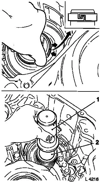
Attach 2 hooked seal rings to pin in main housing – ring
ends have L-shape. Press one ring end into the groove, then hook in
the other end – do not expand hooked seal rings more than
necessary.
|
Drive in needle bearing for reduction clutch using KM-711-3 (2)
and KM-674 (1) until tool comes into contact with main housing.
|
|
|
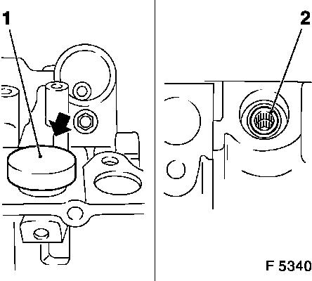
Install needle bearing for selector lever shaft: Place bearing
(2) onto KM-711-1 (1) and drive in to the stop. Drive seal ring for
selector lever shaft flush into main housing with suitable drift
– closed side faces outwards.
|
|
|
Install piston for multi-disc brake B3 (1) and intermediate
drive gear (2) – see operation "Intermediate Drive Gear,
Remove and Install (AF 20)".
Install planetary gear set P1 (3) – see operation
"Planetary Gear Set P1, Remove and Install (AF 20)".
Install pipes (5) and drive shaft assembly (4) with multi-plate
clutch C1 and C2 – see operation "Drive Shaft Assembly with
Multi-plate Clutch C1 and C2, Remove and Install (AF 20)".
Install rear cover (6) with piston C1 – see operation
"Rear Cover with Piston C1, Remove and Install (AF 20)".
|
|
|
Install multi-plate clutch C3 (1) and freewheel F3 with brake
band B4 (2) – see operation "Multi-plate Clutch C3 and
Freewheel F3, Remove and Install (AF 20)".
Install planetary gear set P2 (3) – see operation
"Planetary Gear Set P2, Remove and Install (AF 20)".
Install main housing plate (5) – tightening torque 7 Nm /
5 lbf. ft.
Install fluid screen (4) – tightening torque 7 Nm / 5 lbf.
ft.
|
|
|
Replace seal rings (1).
Insert accumulator piston (2) with cover (4) and spring into
main housing. Install fastening bolt (6) – tightening torque
6 Nm / 4 lbf ft. Install fastening bolt (3) with torsion spring (5)
– tightening torque 10 Nm / 7.5 lbf ft. Engage short arm of
spring in accumulator cover.
Install differential (7) – see operation "Differential,
Remove and Install (AF 20)".
Install parking lock (8) – see operation "Parking Lock,
Remove and Install (AF 20)".
|
|
|
Install freewheel F1 (1) – see operation "Freewheel F1,
Remove and Install (AF 20)".
Install fluid pump assembly (2) with multi-disc brake B1 and B2
– see operation "Fluid Pump Assembly with Multi-disc Brakes
B1 and B2, Remove and Install (AF 20)".
Install valve body (3) – see operation "Valve Body, Remove
and Install (Transmission Removed) (AF 20)".
Attach transmission output speed sensor (4) and transmission
input speed sensor (5) with new seal rings to transmission –
tightening torque 6 Nm / 4 lbf ft.
|
|
|
Attach plug – M8 to main housing – tightening torque
8 Nm / 6 lbf. ft. Attach plug – M18 to main housing –
tightening torque 35 Nm / 26 lbf. ft.
Coat sealing surfaces with sealing compound and attach auxiliary
housing cover to transmission – tightening torque 8 Nm / 6
lbf. ft.
Attach fluid temperature sensor (2) to transmission –
tightening torque 10 Nm / 7.5 lbf. ft.
Attach cover plate (1) to side cover and transmission –
tightening torque 25 Nm / 18 lbf. ft.
|
|
Install converter – see operation "Converter and/or Fluid
Pump Seal Ring, Replace (AF 13-II/AF 17/AF 20/AF 22)". Secure
converter against falling out.
|
Attach fluid drain bolt (3) with new seal ring to transmission
– tightening torque 40 Nm / 29.5 lbf. ft.
Remove transmission assembly from KM-113-2 (1) with KM-694-A
(2).
Remove transmission from KM-694-A.
Install transmission – see operation "Transmission, Remove
and Install (AF 20)".
 Inspect
Check and correct level of transmission fluid – see
operation "Transmission Fluid Level, Check and Correct (AF 13-II/AF
17/AF 20/AF 22)".
|
|
|
