|
Camshafts, Remove and Install
 Remove Remove
| 1. |
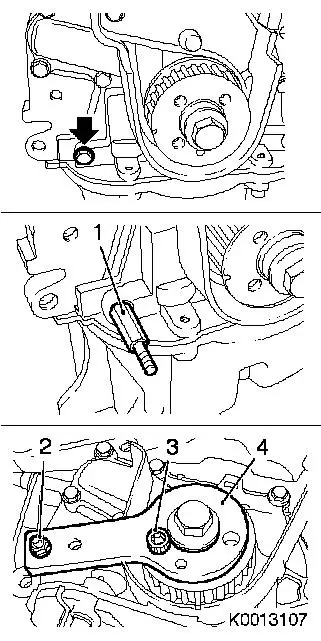
Remove right engine damping block adapter 
|
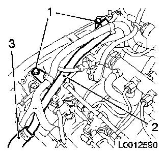
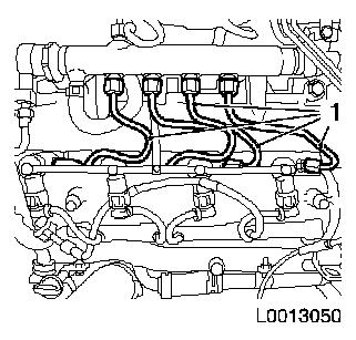
| 2. |
Detach engine venting pipe (2)
| • |
Detach engine venting hose (3) from engine venting pipe
|
|
|
|
| 3. |
Install EN-46789 (1) in camshaft
housing
| • |
Unscrew exhaust camshaft closure bolt
|
|
| 4. |
Set cylinder no. 1 to TDC of combustion stroke
| • |
Rotate crankshaft in direction of engine rotation until
reference drift EN-46789 audibly engages
in exhaust camshaft
|
|
|
|
| 5. |
Remove toothed belt (1)
| • |
Remove toothed belt tension roller
|
|
|
|
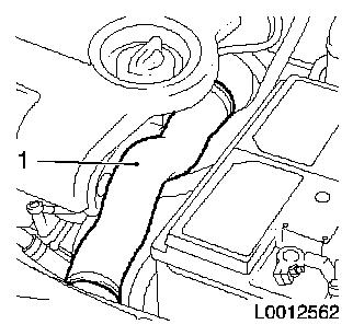
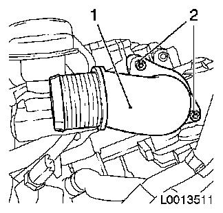
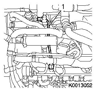
| 6. |
Remove charge air hose (1)
|
|
|
| 7. |
Detach intake connection piece (1) from throttle valve
module
|
|
|
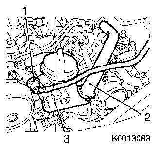
| 8. |
Remove brake servo vacuum line
| • |
Undo quick-release fitting (1)
|
|
| 9. |
Remove engine oil filling nozzle (3)
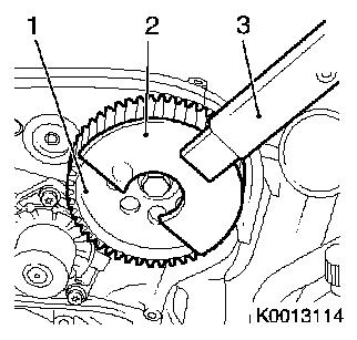
| • |
Detach engine vent hose (2)
|
|
|
|
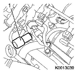
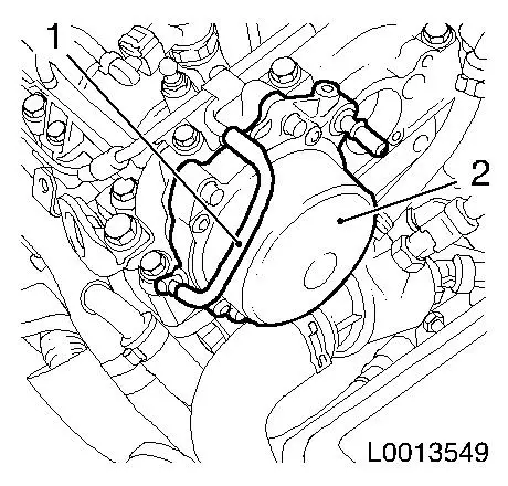
| 10. |
Remove vacuum pump (2)
|
|
|
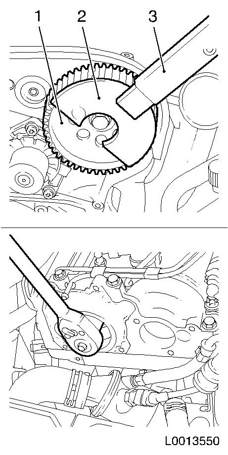
| 11. |
Release 2x camshaft drive gear
Note: 2nd mechanic
needed. Release intake camshaft bolt first.
| • |
Use KM-956-1 (3) in conjunction with
KM-6347 (2)
| – |
Counterhold in drive gear (1) for camshafts
|
|
|
|
|
| 12. |
Release camshaft drive gear (1)
| • |
Use KM-956-1 (3) in conjunction with
KM-6347 (2)
|
|
|
|
| 13. |
Detach vacuum line from cable conduit
|
|
|
| 14. |
Detach engine management wiring harness
| • |
Disconnect 8x wiring harness plug
|
| • |
Charge pressure control solenoid valve
|
| • |
Pressure-regulating valve
|
|
| 15. |
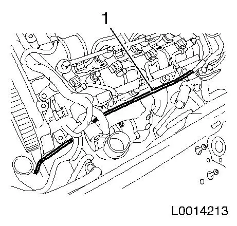
Remove vacuum line (1)
| • |
Detach 4x vacuum hoses
Note: Mark vacuum
hoses
|
|
|
|
| 16. |
Detach leak oil line (1)
Note: Oil leak line may
not be detach from damping case for fuel return
| • |
Release 4x retaining clamp (arrows)
|
|
|
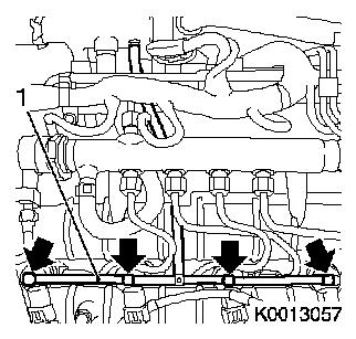
|
Important: When releasing the
retaining nut, counterhold with open-ended wrench against the
injector
|
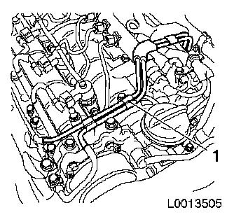
| 17. |
Detach 4x high pressure line (1), pressure chamber on
injector
Important: Seal injector and
pressure chamber openings with protective caps
1)
|
| • |
Release 8x retaining nut
|
|
|
|
Important: When releasing the
retaining nut, counterhold with open-ended wrench against the
connection for the high pressure fuel pump
|
| 18. |
Remove high pressure line (1) from high pressure pump to
pressure chamber
Important: Seal pressure chamber
and high pressure pump with sealing caps
1)
|
| • |
Unscrew 2x union nuts
|
|
|
|
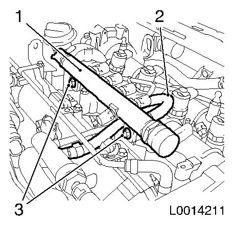
| 19. |
Remove accumulator (1)
|
|
|
| 20. |
Detach bracket (1) for toothed belt cover
|
|
|
| 21. |
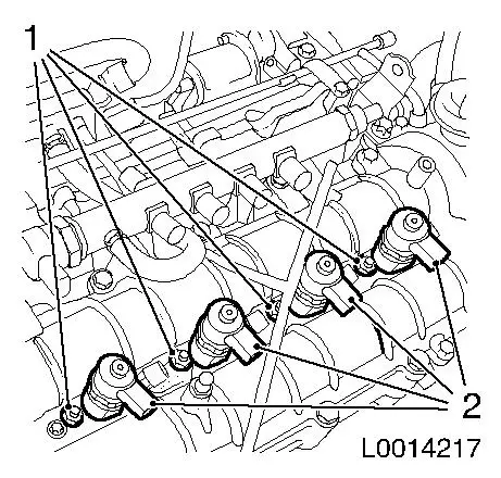
Remove 4x injector (2)
Note: If injectors
cannot be removed by hand, use EN-46786
in conjunction with KM-328-B
Important: Seal apertures of
injectors and of pressure chamber with protective caps
|
| • |
Remove 4x injector with bracket
|
|
|
|
|
| 22. |
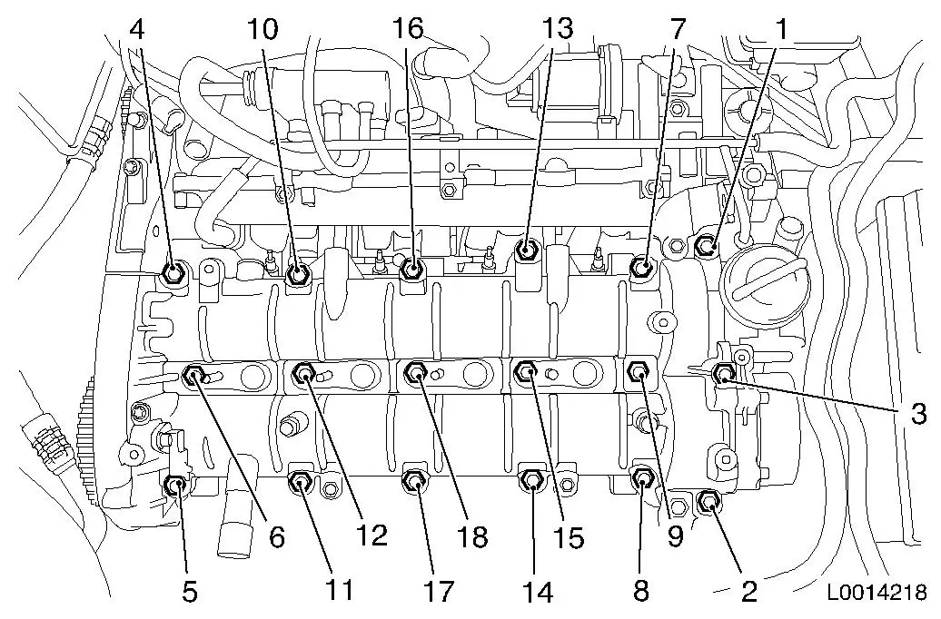
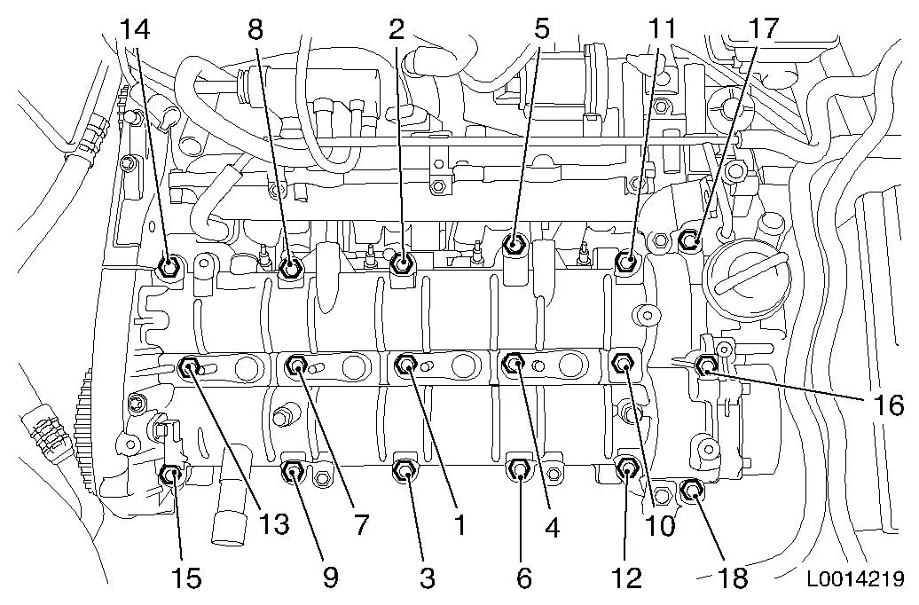
Detach camshaft housing
Note: Unscrew bolts
carefully in the tightening sequence stated (1 - 18). Camshaft
housing must be released evenly from cylinder head.
|
|
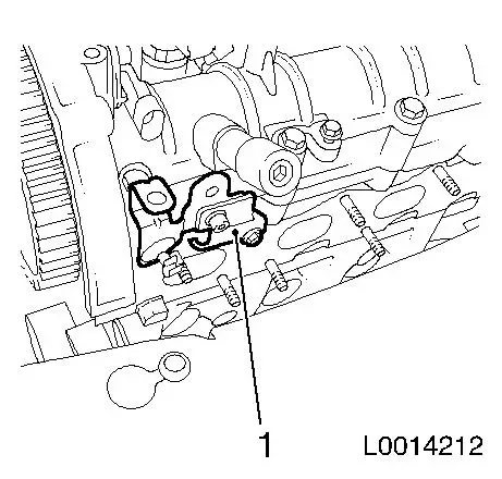
| 23. |
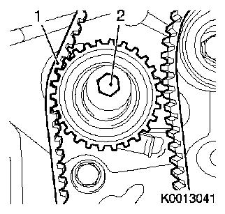
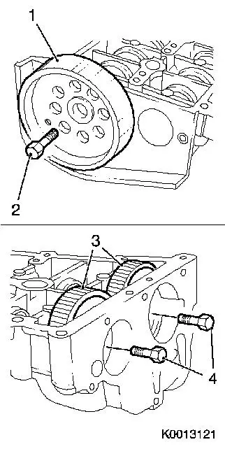
Detach 2x camshaft drive gear (3)
|
| 24. |
Remove camshaft sprocket (1)
|
|
|
| 26. |
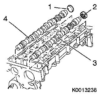
Remove closure cap (1) of intake camshaft
Note: Do not damage
sealing surface
| • |
Remove with suitable tool
|
|
| 27. |
Remove camshaft seal ring (2)
Note: Do not damage
sealing surface.
| • |
Remove with suitable tool
|
|
| 28. |
Remove 2x camshaft (3) and (4)
|
|
|
 Install
| 29. |
Install 2x camshaft
| • |
Coat bearing surfaces with engine oil
|
| • |
Insert 2x camshaft drive gear
|
Important: Use EN-46780
|
| • |
Attach seal ring for camshaft sprocket
|
| • |
Attach closure cap for intake camshaft
|
Important: Guide pin in camshaft
drive gear must engage in guide slot in camshaft sprocket
|
| • |
Attach camshaft drive gear
|
|
| 30. |
Set 2x camshaft to TDC of combustion stroke for cylinder 1
| • |
Attach EN-46789 to exhaust
camshaft
|
| • |
Attach EN-46789-100 to intake
camshaft
|
| • |
Ensure correct installation position
Note: Reference drifts
must engage audibly
|
|
| 31. |
Cleaning work
| • |
Camshaft housing, cylinder head, vacuum pump
|
|
| 32. |
Position camshaft housing
|
|
| 33. |
Tighten camshaft housing
| • |
Tighten 18x bolt in the stated order (1 - 18) 25 Nm
Note: Note different
bolt lengths
|
|
|
| 34. |
Tighten 2x camshaft drive gear
| • |
Tighten 2x new bolt 120 Nm
Note: 2nd mechanic
required
|
|
| 35. |
Clean 4x injector casing
Note: To clean the
injector seats, insert EN-47632 with
coarse fleece in the injector casing and pre-clean injector seat by
turning. Then complete cleaning process with fine fleece.
|
| 36. |
Install 4x injector
| • |
Insert 4x injector with bracket
Note: Note sequence,
cylinder 4, 3, 2, 1
|
|
| 37. |
Attach bracket, toothed belt cover
|
Important: When tightening the
retaining nut on the counterhold on the connection for the fuel
high pressure pump with open-ended wrench
|
| 39. |
Attach new high-pressure pump high-pressure line to pressure
chamber
| • |
Tighten 2x retaining nut
|
|
Important: When tightening the
retaining nut, counterhold against the injector with open-ended
wrench, Use new pressure lines
|
| 40. |
Attach 4x high pressure line for pressure chamber to
injector
| • |
Tighten 8x retaining nut
|
|
| 41. |
Attach oil leak line
| • |
Clip 4x oil leak line into injector
|
|
| 42. |
Install vacuum line
| • |
Connect 4x vacuum hoses
Note: Pay attention to
marks
|
|
| 43. |
Attach engine management wiring harness
| • |
Connect 8x wiring harness plug
|
| • |
Charge pressure control solenoid valve
|
| • |
Pressure-regulating valve
|
|
| 44. |
Clip vacuum line into cable conduit
|
| 45. |
Clean sealing surfaces.
| • |
Vacuum pump, engine oil filler port, throttle valve module
|
|
| 46. |
Install vacuum pump
| • |
Tighten 4x new bolt 5 Nm +
50°
|
|
| 47. |
Install engine oil filling nozzle
| • |
Tighten 3x bolts
Note: Recut thread
before re-using and insert bolt with locking compound (red). The
maximum installation time including torque check is 10 minutes
|
| • |
Attach engine venting hose
|
|
Warning: Connection must audibly
engage
|
| 48. |
Connect brake servo vacuum line
|
| 49. |
Attach intake port to throttle valve module
| • |
Replace gasket
Note: Coat with special
grease (white)
|
|
| 50. |
Attach intercooler charge air pipe to throttle body
|
| 52. |
Install toothed belt tension roller
Note: Insert tension
roller in guide
| • |
Screw in bolt
Note: Clean thread
before re-using and insert bolt with locking compound (red). The
maximum installation time including torque check is 10 minutes.
|
|
Important: Tightened end must be
taut
|
| 53. |
Install toothed belt
Note: Observe direction
of rotation
|
| 54. |
Lock crankshaft with EN-46788
| • |
Tighten stud bolt (1) EN-46788
|
| • |
Attach positioning disk (4) EN-46788
|
|
|
|
| 55. |
Raise vehicle by its full height
|
Important: Toothed belt tension
roller must be at maximum tension
|
| 56. |
Tension the toothed belt
| • |
Tighten bolt - toothed belt tension roller
|
|
| 57. |
Lower vehicle by its full height
|
| 58. |
Fasten camshaft drive gear
| • |
Counterhold drive gear with EN-47634
in combination with KM-956-1
|
|
| 59. |
Raise vehicle by its full height
|
| 60. |
Toothed Belt Tension, Adjust
| • |
Tension the toothed belt
Note: Push adjusting
lever in direction of arrow with a screwdriver (5) until pointer
(4) of toothed belt tension roller aligns with mark (2)
|
| • |
Tighten bolt, toothed belt tension roller (3) 25 Nm
|
|
|
|
| 61. |
Lower vehicle by its full height
|
| 62. |
Remove positioning disk EN-46788
|
| 63. |
Turn crankshaft 720° in the
direction of rotation of the engine
| • |
Rotate crankshaft in direction of engine rotation until
reference drift EN-46789 audibly engages
in exhaust camshaft
|
|
| 64. |
Check crankshaft setting with EN-46788
Note: If EN-46788 cannot be fitted, repeat the toothed belt
positioning procedure
| • |
Attach positioning disk EN-46788
|
| • |
Remove EN-46788
| – |
Unscrew stud bolt EN-46788
|
|
|
| 65. |
Remove EN-46789 from camshaft
housing
| • |
Tighten closure bolt 16 Nm
|
|
| 66. |
Attach engine venting pipe
| • |
Attach engine venting hose to engine venting pipe
|
|
| 67. |
Install right engine damping block adapter
|
1 ) Protective caps are available from the Opel
parts catalogue under catalogue number 45 06 154 / part number:
9201697
|
