|
All Valve Stem Seals, Replace
| Spezialwerkzeugliste: |
- KM-194-E
- KM-6152
- KM-840
- MKM-6086
- MKM-6086-100-15
- MKM-6086-200
|
 Remove Remove
Important: Observe correct
allocation and sequence
|
| 3. |
Remove 8x roller cam follower, intake side
|
Important: Observe correct
allocation and sequence
|
| 4. |
Remove 8x roller cam follower, exhaust side
|
| 5. |
Engage gear and put the handbrake on
Note: All the wheels
must be in contact with the ground
|
| 6. |
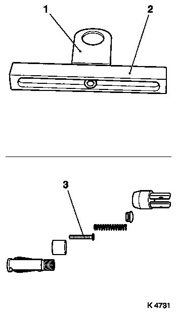
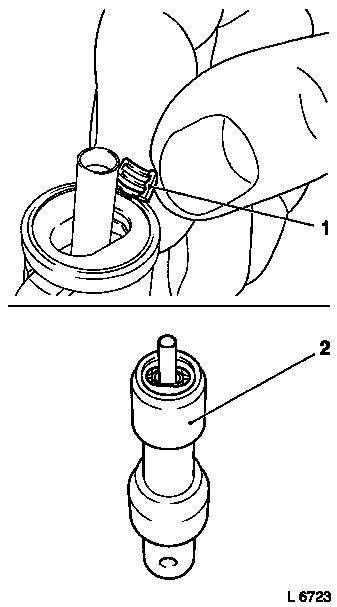
Prepare automatic valve spring lever MKM-6086
| • |
Adjust supports
Note: Fit support heads
(1) centrally on support feet (2).
|
| • |
Complete lever arm
| – |
With joint, disassembly head
|
|
| • |
Complete MKM-6086-200 assembly
head
| – |
Use MKM-6086-100-15 (3). Insert
pressure piece "6J".
Note: Note
manufacturer's provisions.
|
|
|
|
|
|
| 7. |
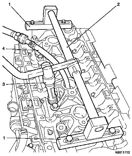
Attach automatic valve spring lever
| • |
Attach 2x supports (1)
| – |
At position camshaft bearing cap 1 and 5
|
| – |
Slide assembly shaft (2) with joint into supports
Note: Align assembly
shaft centrally via spark plug bore.
|
|
| • |
Attach lever arm
Note: Removal head (3)
must point towards the intake side.
|
|
| 8. |
Install compressed air adapter (4)
| • |
Screw into spark plug thread of cylinder 1
|
| • |
Apply compressed air to cylinder 1
|
|
|
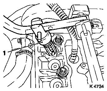
| 9. |
Remove 2x intake valve spring, cylinder 1
| • |
Carefully push valve springs downwards
| – |
With lever arm
Note: Removal head (1)
must be positioned vertically over the valve stem.
|
|
Important: Observe correct
assignment.
|
| • |
Take out valve cotters, valve discs, valve springs
Note: Do not use any
magnetic tools.
|
|
|
|
 Install
| 10. |
Renew 2x valve stem seals
| • |
Place 2x new valve stem seal on to valve stem
|
|
|
|
| 11. |
Install 2x intake valve spring, cylinder 1
| • |
Insert valve springs, valve disks
|
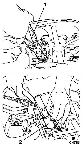
| • |
Insert valve cotters (1) into assembly head
| – |
Slide plastic clamping sleeve (2) in direction of lever arm
mount
|
Important: Insert valve cotters
with tapered end towards valve.
|
| – |
Push plastic clamping sleeve towards valve
|
|
| • |
Attach assembly head to lever arm
|
| • |
Carefully push valve springs downwards
Important: Assembly head must
stand vertically above valve stem. Valve cotters must engage
audibly.
|
| – |
with lever arm
|
|
|
|
|
Important: Do not make a 2nd
attempt without checking that both valve cotters are seated in the
assembly head. Check seat of valve cotters. Ensure pressure is
being applied.
|
| 12. |
Check installation position
|
| 13. |
Transfer lever arm
| • |
Insert lever arm
Note: Removal head must
point towards the exhaust side.
|
|
| 14. |
Remove 2x exhaust valve spring, cylinder 1
| • |
Carefully push valve springs downwards
| – |
With lever arm
Note: Dismantling head
must be positioned vertically over the valve stem
|
|
Important: Observe correct
assignment.
|
| • |
Take out valve cotters, valve discs, valve springs
Note: Do not use any
magnetic tools.
|
|
| 15. |
Renew 2x valve stem seals
| • |
Place 2x new valve stem seal on to valve stem
|
|
| 16. |
Install 2x exhaust valve spring, cylinder 1
| • |
Insert valve springs, valve disks
|
| • |
Insert valve cotters into assembly head
| – |
Push plastic clamping sleeve towards lever arm mounting
|
Important: Insert valve cotters
with tapered end towards valve.
|
| – |
Push plastic clamping sleeve towards valve
|
|
| • |
Attach assembly head to lever arm
|
| • |
Carefully push valve springs downwards
Important: Assembly head must
stand vertically above valve stem. Valve cotters must engage
audibly.
|
| – |
with lever arm
|
|
|
Important: Do not make a 2nd
attempt without checking that both valve cotters are seated in the
assembly head. Check seat of valve cotters. Ensure pressure is
being applied.
|
| 17. |
Check installation position
|
| 18. |
Transfer compressed air adapter
| • |
Interrupt compressed air feed
|
| • |
Unscrew from spark plug thread of cylinder 1
|
| • |
Screw into spark plug thread, cylinder 4
|
| • |
Apply compressed air to cylinder 4
|
|
| 19. |
Transfer lever arm
| • |
Attach removal head
| – |
Insert pin
Note: Removal head must
point towards the exhaust side.
|
|
|
| 20. |
Remove 2x exhaust valve spring, cylinder 4
|
| 21. |
Renew 2x valve stem seals
|
| 22. |
Install 2x exhaust valve spring, cylinder 4
|
| 23. |
Check installation position
|
| 24. |
Transfer lever arm
| • |
Attach lever arm
Note: Removal head must
point towards the intake side.
|
|
| 25. |
Remove 2x intake valve spring, cylinder 4
|
| 26. |
Renew 2x valve stem seals
|
| 27. |
Install 2x intake valve spring, cylinder 4
|
| 28. |
Check installation position
|
| 29. |
Interrupt compressed air feed
|
| 31. |
Set cylinder 2 to TDC of combustion stroke
| • |
Turn crankshaft evenly (180°)
Note: Torsional
vibration damper auxiliary marking must be flush with timing case
cover marking.
|
|
| 32. |
Engage gear and put the handbrake on
Note: All the wheels
must be in contact with the ground
|
| 33. |
Transfer lever arm
| • |
Attach removal head
Note: Removal head must
point towards the intake side.
|
|
| 34. |
Transfer compressed air adapter
| • |
Unscrew from spark plug thread, cylinder 4
|
| • |
Screw into spark plug thread of cylinder 2
|
| • |
Apply compressed air to cylinder 2
|
|
| 35. |
Remove 2x intake valve spring, cylinder 2
|
| 36. |
Renew 2x valve stem seals
|
| 37. |
Install 2x intake valve spring, cylinder 2
|
| 38. |
Check installation position
|
| 39. |
Transfer lever arm
| • |
Attach lever arm
Note: Removal head must
point towards the exhaust side.
|
|
| 40. |
Remove 2x exhaust valve spring, cylinder 2
|
| 41. |
Renew 2x valve stem seals
|
| 42. |
Install 2x exhaust valve spring, cylinder 2
|
| 43. |
Check installation position
|
| 44. |
Transfer lever arm
| • |
Attach removal head
Note: Removal head must
point towards the exhaust side.
|
|
| 45. |
Transfer compressed air adapter
| • |
Unscrew from spark plug thread, cylinder 2
|
| • |
Screw into spark plug thread, cylinder 3
|
| • |
Apply compressed air to cylinder 3
|
|
| 46. |
Remove 2x exhaust valve spring, cylinder 3
|
| 47. |
Renew 2x valve stem seals
|
| 48. |
Install 2x exhaust valve spring, cylinder 3
|
| 49. |
Check installation position
|
| 50. |
Transfer lever arm
| • |
Attach lever arm
Note: Removal head must
point towards the intake side.
|
|
| 51. |
Remove 2x intake valve spring, cylinder 3
|
| 52. |
Renew 2x valve stem seals
|
| 53. |
Install 2x intake valve spring, cylinder 3
|
| 54. |
Check installation position
|
| 55. |
Detach automatic valve spring lever
|
| 56. |
Remove compressed air adapter
| • |
Interrupt compressed air feed
|
|
| 58. |
Adjust TDC of combustion stroke, cylinder 4
| • |
Turn crankshaft evenly (180°)
Note: Torsional
vibration damper TDC notch must be flush with timing case cover
marking.
|
|
| 59. |
Visually check components
| • |
Camshafts, camshaft bearing cap, hydraulic valve lifter,
cylinder head, spark plugs
|
|
| 60. |
Insert 8x roller cam follower, exhaust side
Important: Observe correct
assignment.
|
| • |
Lightly coat sliding surfaces with engine oil
|
|
| 61. |
Insert 8x roller cam follower, intake side
Important: Observe correct
assignment.
|
| • |
Lightly coat sliding surfaces with engine oil
|
|
| 62. |
Install 4x spark plug
| • |
Tighten using KM-194-E 25 Nm
|
|
|
