|
Engine, Remove and Install
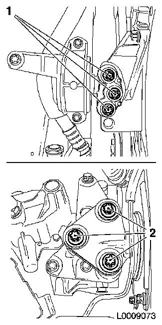
| 2. |
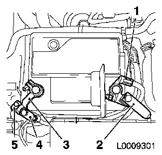
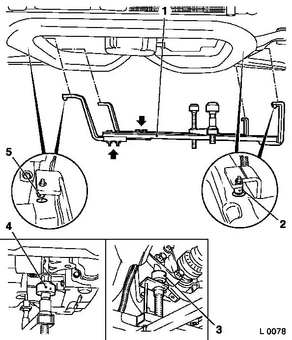
Detach earth cable
| • |
Detach earth cables (4) and (5) from earth terminal (3)
|
| • |
Detach earth connection from negative terminal
|
|
| 3. |
Detach positive cable
| • |
Detach positive cable (2) from positive terminal (1)
|
| • |
Detach positive connection from positive terminal
|
|
|
|
| 4. |
Empty climate control system 
|
| 5. |
Remove lower driver's side cover
| • |
Release 2x retaining clips
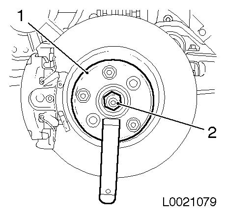
|
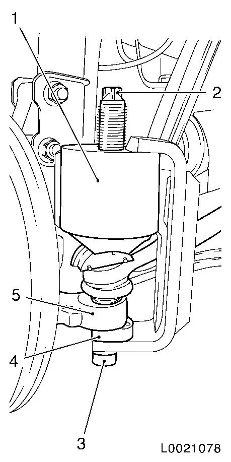
|
| 6. |
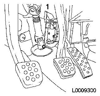
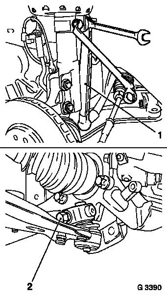
Detach steering column intermediate shaft
| • |
Set steering wheel in straight ahead position, remove ignition
key and engage steering lock
|
|
|
|
| 7. |
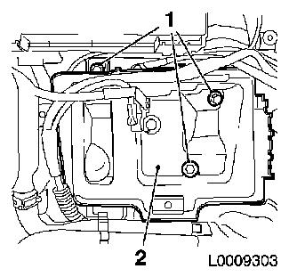
Remove battery
| • |
Detach positive connection from positive terminal
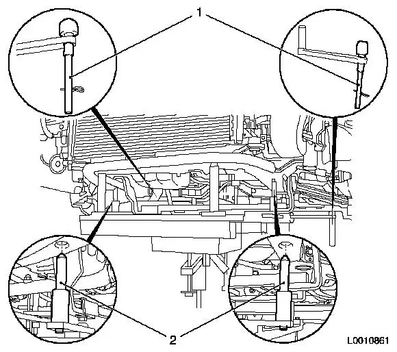
|
| • |
Remove battery bracket (2)
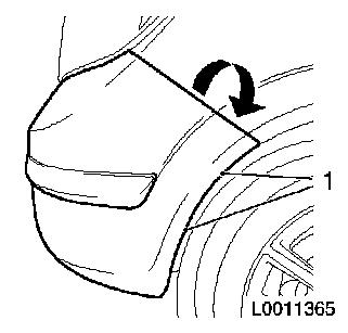
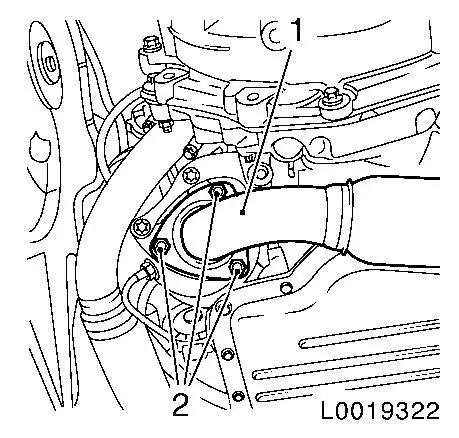
|
|
|
|
| 8. |
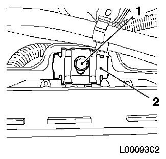
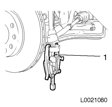
Disconnect charge pressure sensor wiring harness plug
|
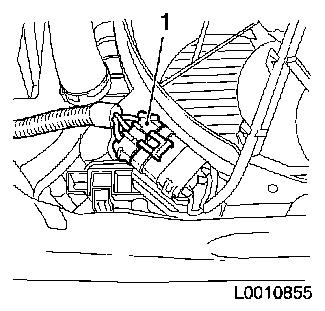
| 9. |
Disconnect upper cooling module wiring harness
| • |
Disconnect wiring harness connector.
|
| • |
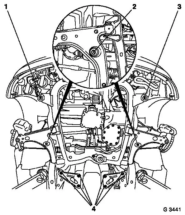
Unclip relay from bracket
|
|
| 10. |
Remove battery support (2)
| • |
Detach wiring harness from battery support
|
|
|
|
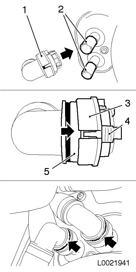
| 11. |
Remove air cleaner housing with mass air flow sensor
| • |
Disconnect air mass flow meter wiring harness plug
|
| • |
Detach air intake hose from air intake pipe
|
| • |
Unscrew bolt
Note: The wiring
harness plug cannot be disconnected without first removing the mass
air flow sensor from the air cleaner housing
|
|
| 12. |
Detach brake servo vacuum line from intake manifold
| • |
Disconnect quick-release fitting
|
| • |
Unclip vacuum line from bracket
|
|
| 13. |
Remove air intake pipe
| • |
Remove engine vent hose from cylinder head cover
Note: Seal air intake
pipe to turbocharger
|
|
| 14. |
Place collecting basin underneath.
|
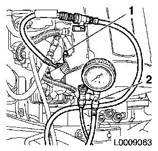
| 15. |
Relieve fuel pressure using KM-J-34730-91 at test connection
Note: Collect exiting
fuel in a suitable container - observe safety regulations and
national legislation.
|
|
|
| 16. |
Detach fuel supply line (2)
| • |
Undo quick-release fitting with KM-796-A
|
|
| 17. |
Detach fuel return line (1)
| • |
Undo quick-release fitting with KM-796-A
|
|
|
|
| 18. |
Detach venting line of tank vent valve
| • |
Undo quick-release fitting with KM-796-A
|
|
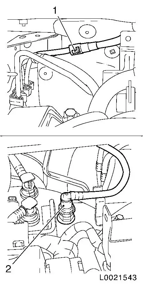
| 19. |
Disconnect fuel vapour separator line
| • |
Undo quick-release fitting (1)
|
|
| 20. |
Detach brake servo vacuum line from intake manifold
| • |
Disconnect quick-release fitting (2)
|
|
|
|
| 22. |
Raise vehicle by half its height
|
| 23. |
Remove 2x front wheels
|
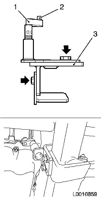
| 24. |
Remove front panelling (3)
| • |
Remove 5x body-bound rivets (2)
|
|
|
|
| 25. |
Place collecting basin underneath.
|
| 26. |
Detach high-pressure headlamp cleaning system hose from
reservoir
| • |
Disconnect quick-release fitting
Note: Escaping
fluid
|
|
| 27. |
Remove front panelling
Note: Use a second
person
Note: Push front
panelling upwards at side and pull out of bracket
| • |
Detach front panelling from bracket
|
| • |
Unclip outside temperature sensor
|
|
|
|
| 28. |
Remove engine splash guard (right-hand)
| • |
Remove 2x body-bound rivet
|
|
| 29. |
Detach 2x axle shafts from wheel hub
| • |
Unscrew 2x nuts (2) from axle shaft
| – |
Counterhold with KM-6610 (1) at front
wheel hub
|
|
|
|
|
| 30. |
Undo tie rod end (6) from steering knuckle (5)
| • |
Attach CH-47658 (1)
| – |
Position CH-47658 (1) with suitable
sleeve (4)
Note: In order to
centre CH-47658 , CH-47658 must be used with the appropriate socket
wrench groove (3).
|
| – |
Fasten CH-47658 (1) to hexagonal
section (2)
|
|
| • |
Unscrew tie rod end nut
|
|
|
|
| 31. |
Press tie rod out of steering knuckle using KM-161-B (1) in conjunction with hook KM-161-2
|
|
|
| 32. |
Detach 2x swing arms (1) from spring strut support tube
| • |
Use open-ended wrench to hold against the flat surfaces
|
|
| 33. |
Detach guide joint from steering knuckle
| • |
Detach 2x screw connections
|
| • |
Expand steering knuckle with KM-915
(2)
|
| • |
Pull guide joint out of steering knuckle
|
|
| 34. |
Press axle shaft out of wheel hub
Note: Do not pull the
steering knuckle outwards when doing so. Use a wheel hub puller if
necessary.
|
|
|
| 35. |
Raise vehicle by half its height
|
| 36. |
Release left wheel housing inner panelling
| • |
Remove 3x body-bound rivets
|
|
| 37. |
Detach cooling module wiring harness (1)
| • |
Disconnect wiring harness connector.
|
|
|
|
| 38. |
Place collecting basin underneath.
|
| 39. |
Drain coolant
| • |
Unscrew coolant drain bolt
|
| • |
Screw in coolant drain bolt
|
|
| 40. |
Detach catalytic converter control's oxygen sensor wiring
harness
| • |
Disconnect wiring harness connector.
|
|
| 41. |
Remove front exhaust pipe
| • |
Detach front exhaust pipe (1) from catalytic converter
|
| • |
Detach front exhaust pipe from middle silencer
|
|
|
|
| 42. |
Remove right drive shaft from intermediate shaft
Note: Drive out with
soft metal drift
Note: Oil flows out.
Place collecting pan underneath and seal the openings with a
plug.
|
| 43. |
Carefully place the axle shaft down
Note: Do not lay it on
the boots.
|
| 44. |
Insert KM-6173 (3)
| • |
Slacken 4x bolts (arrows) and hand-tighten
|
| • |
Align KM-6173 at front axle body
|
| • |
Wind up the support bearing (1)
| – |
Journal (2) must sit in mount at cylinder block
|
|
|
|
|
| 45. |
Attach KM-6001-A (1)
Note: Attaching KM-6001-A guarantees perfect alignment of the
drive unit with the front axle body
| • |
Slacken 3x bolts (arrows) in adjusting rails
|
| • |
Insert KM-6001-A
| – |
The journals (2) and (5) must sit in the guide holes of the
front axle body
|
|
| • |
Tighten 3x bolts in adjusting rails
|
| • |
Adjust support bearings, front (4) and rear (3)
| – |
Raise support bearings up to the stop on the guide journals
Note: The guide
journals must be seated free from play in the support bearings
|
|
|
|
|
| 46. |
Lower vehicle by its full height
|
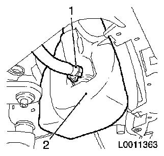
| 47. |
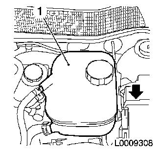
Remove coolant expansion tank (1)
| • |
Pull out of bracket in direction of arrow
|
|
|
|
| 48. |
Detach 2x shift cables
|
| 49. |
Disconnect the pressure line for central disengagement at the
clutch housing
| • |
Release clamp with screwdriver in direction of arrow and
remove
|
| • |
Lock retaining clamp
Note: Seal of line
ends
|
|
| 50. |
Disconnect steering wiring harness
| • |
Remove fuse carrier cover
|
| • |
Detach positive cable from fuse carrier
|
| • |
Disconnect wiring harness connector.
|
| • |
Expose wiring harness
| – |
Remove 2x from wiring harness bracket
|
|
|
| 51. |
Disconnect wiring harness plug of reversing lights
|
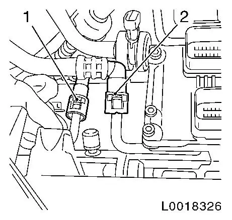
| 52. |
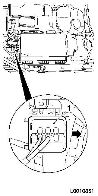
Disconnect wiring harness plug (1)
| • |
Release retainer in direction of arrow
|
|
|
|
| 53. |
Disconnect engine wiring harness
| • |
Unclip oxygen sensor wiring harness plug from bracket
|
| • |
Disconnect wiring harness connector.
|
| • |
Disconnect wiring harness plug of engine control unit
|
| • |
Unclip 2x retaining clips
|
|
| 54. |
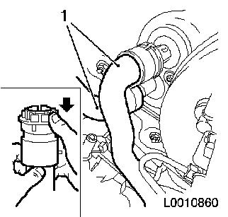
Detach coolant hoses (1) from heater core
Note: Mark assignment
using coloured markings
| • |
Place collecting basin underneath.
|
| • |
Release 2x quick-release fittings in direction of arrow
|
|
|
|
| 55. |
Disconnect refrigerant line (low pressure side)
|
| 56. |
Detach refrigerant line from condenser
|
| 57. |
Detach right engine damping block from engine damping block
bracket
|
| 58. |
Detach left engine damping block from engine damping block
bracket
|
|
|
| 59. |
Raise vehicle by its full height
|
|
| 60. |
Attach KM-904 with KM-6390
| • |
Attach to hydraulic lifter
Note: Use hydraulic
jack that can be lowered to a height of at least 100 cm
|
| • |
Lower centring pins (1)
|
| • |
Place under front axle body, ensure there is no play
| – |
Centring pins (2) must engage in the relevant holes in the
front axle body
|
|
|
|
Important: It is not permissible
to disassemble the front axle body with an impulse or impact
screwdriver
|
| 61. |
Remove front axle body
| • |
Unscrew 10x bolts (1, 2, 3, 4)
Note: Note different
bolt lengths
|
|
|
|
Important: Ensure that no
attached parts are damaged
|
| 62. |
Move out front axle body
Note: Use a second
person
|
Important: Ensure that no
attached parts are damaged
|
| 63. |
Move front axle body back in
Note: Use a second
person
|
Important: It is not permissible
to assemble the front axle body with an impulse or impact
screwdriver
|
| 64. |
Fit front axle body
| • |
Tighten 6x new bolt 90 Nm + 45° +
15°
|
|
| 65. |
Remove KM-904 with KM-6390
| • |
Detach KM-904 and KM-6100 from hydraulic jack
|
|
| 66. |
Lower vehicle by its full height
|
| 67. |
Attach right engine damping block to engine damping block
adapter
|
| 68. |
Attach left engine damping block to engine damping block
adapter
|
| 69. |
Attach refrigerant line to condenser
|
| 70. |
Connect refrigerant line (low pressure side)
|
Important: It is imperative to
adhere to the following assembly order
|
| 71. |
Attach cooling hoses to heater core
| • |
Fit 2x quick release fittings (1) onto heater core connection
port (2) as far as they will go
Note: Pay attention to
coloured markings
|
| • |
Slide the 2x quick-release fitting catches (3) in the direction
of the arrow all the way to the stop by simultaneously pressing the
release buttons (4)
| – |
The colour rings (5) must be visible
|
|
| • |
Check that quick release fittings are correctly seated and that
the colour rings (5) are visible
|
|
|
|
| 72. |
Connect engine wiring harness
| • |
Connect wiring harness plug of engine control unit
|
| • |
Clip in 2x retaining clips
|
| • |
Fix wiring harness plug
|
| • |
Clip oxygen sensor wiring harness plug to bracket
|
|
| 73. |
Fix wiring harness plug
Note: Front wiring
harness plug to fuse carrier
|
| 74. |
Connect wiring harness plug, reverse gear
|
| 75. |
Connect steering wiring harness
| • |
Clip in 2x wiring harness brackets
|
| • |
Attach positive cable to fuse carrier
|
| • |
Fix wiring harness plug
|
| • |
Install fuse carrier cover
|
|
| 76. |
Connect central release pressure line at clutch housing
| • |
Connect quick release fitting
|
|
| 77. |
Attach 2x shift cables
|
| 78. |
Raise vehicle by its full height
|
| 81. |
Install right drive shaft in intermediate shaft
|
| 82. |
Install front exhaust pipe
| • |
Attach front exhaust pipe with new gasket to catalytic
converter 20 Nm
|
| • |
Attach front exhaust pipe to middle silencer
|
|
| 83. |
Attach catalytic converter control oxygen sensor wiring
harness
| • |
Fix wiring harness plug
|
|
| 84. |
Lower vehicle by half its height
|
| 85. |
Attach cooling module wiring harness
| • |
Fix wiring harness plug
|
|
| 86. |
Fit left wheel housing inner panelling
| • |
Install 3x body-bound rivets
|
|
| 87. |
Install 2x axle shafts into wheel hub
| • |
Tighten 2x new nuts
| – |
Counterhold at wheel hub with KM-468-B
|
|
|
| 88. |
Attach 2x guide joints to steering knuckle
| • |
Tighten 2x new screwed joint 100
Nm
|
|
| 89. |
Attach 2x swing arms to spring strut support tube
| • |
Tighten 2x new nut 65 Nm
Note: Use spanner to
counterhold against flat surface
|
|
| 90. |
Attach 2x tie rods to steering knuckle
| • |
Tighten 2x new nut 50 Nm
|
|
| 91. |
Install right engine splash guard
| • |
Install 2x body-bound rivets
|
|
| 92. |
Insert front panelling
| • |
Second mechanic
Note: Slide side front
panelling into bracket
|
| • |
Attach front panelling to bracket
|
| • |
Clip in outside temperature sensor
|
|
| 93. |
Fit front panelling
| • |
Install 5x body-bound rivets
|
|
| 94. |
Attach high-pressure headlamp cleaning hose to reservoir
| • |
Connect quick release fitting
|
|
| 96. |
Lower vehicle by half its height
|
| 97. |
Fasten 2x front wheels 110 Nm
|
| 98. |
Install vacuum reservoir vacuum line to turbocharger
|
| 99. |
Attach venting line of tank vent valve
| • |
Connect quick release fitting
|
|
| 100. |
Attach fuel return line to fuel rail
|
| 101. |
Attach fuel supply line to fuel rail
|
| 102. |
Install air intake pipe.
Note: Install air
intake pipe connection to turbocharger
| • |
Attach engine vent hose to cylinder head cover
|
| • |
Fasten clamp; tighten bolt
|
|
| 103. |
Attach brake servo vacuum line to intake manifold
| • |
Connect quick release fitting
|
| • |
Clip vacuum line into bracket
|
|
| 104. |
Install air cleaner housing with mass air flow sensor
| • |
Insert the air cleaner housing
|
| • |
Attach air intake hose to air intake pipe
|
| • |
Connect mass air flow meter wiring harness plug
|
|
| 105. |
Attach brake bleeder unit to bleeder valve
| • |
Remove valve cap from connecting piece's bleeder valve
|
| • |
Attach MKM-6174-1 to bleeder
valve
|
|
| 106. |
Attach brake bleeder unit to brake fluid reservoir
| • |
Attach brake bleeder unit adapter to brake fluid reservoir
|
| • |
Attach MKM-6174-2 to brake bleeder
unit adapter
|
|
| 107. |
Bleed clutch actuation
| • |
Activate brake bleeder unit
|
| • |
Close bleeder valve hand-tight
| – |
Deactivate brake bleeder unit
|
|
|
| 108. |
Detach brake bleeder unit from brake fluid reservoir
| • |
Detach brake bleeder unit adapter from brake fluid
reservoir
|
| • |
Fit brake fluid reservoir cover
|
|
| 109. |
Bleed transmission housing pressure line for central
disengagement
Note: Second
mechanic
|
| 110. |
Detach brake bleeder unit from bleeder valve
|
| 111. |
Check and correct brake fluid level
|
| 112. |
Install battery holder
| • |
Attach wiring harness to battery support
|
|
| 113. |
Insert coolant expansion tank in bracket
|
| 114. |
Connect upper cooling module wiring harness
| • |
Fix wiring harness plug
|
| • |
Clip relay into bracket
|
|
| 115. |
Connect charge pressure sensor wiring harness plug
|
| 116. |
Install battery
| • |
Install battery bracket
|
| • |
Attach positive connection to positive terminal
|
|
| 117. |
Attach positive cable to positive terminal
|
| 118. |
Connect battery
| • |
Attach ground connection to ground terminal
|
|
| 119. |
Attach earth cable to earth terminal
|
| 120. |
Fill with coolant and correct coolant level
|
| 121. |
Top up climate control system
|
| 123. |
Attach steering intermediate shaft
| • |
Coat bolts with bolt locking compound.
|
|
| 124. |
Install lower driver's side cover
| • |
Lock 2x retaining clips
|
|
| 125. |
Programme transient memory
|
|
