|
Remove and install gearshift module (M20 MTA)
 Remove Remove
Important: Follow Easytronic
safety guidelines .
|
| 1. |
Remove clutch module
|
Important: The electronic control
unit may only be removed and reinstalled once. If the electronic
control unit is removed again, it must be replaced.
|
| 3. |
Remove electronic control unit 
|
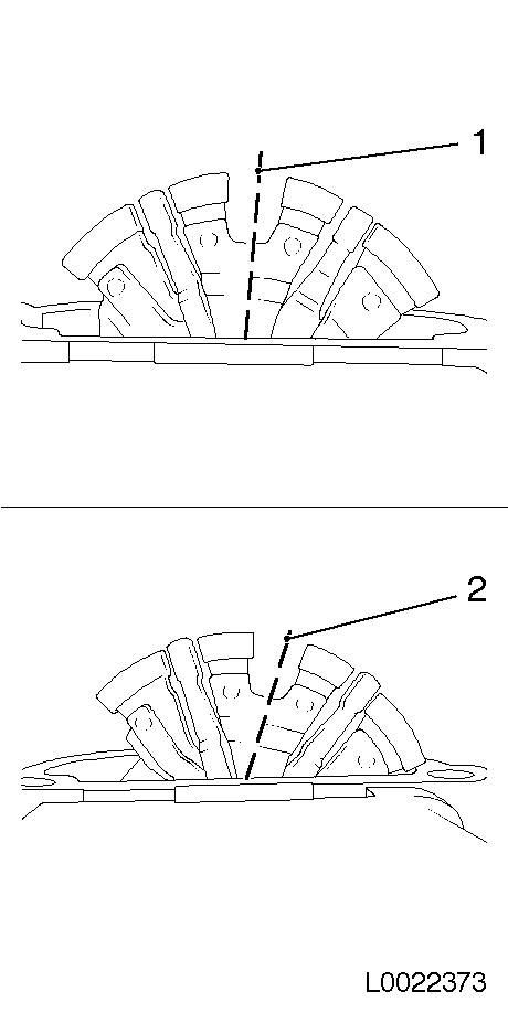
| 4. |
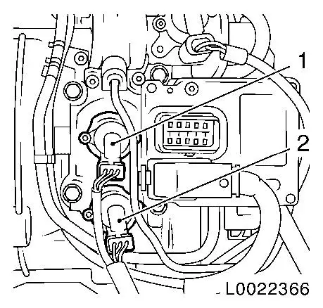
Release 2x wiring harness plugs and disconnect
| • |
from shift position sensor (2)
|
| • |
from selector position sensor (1)
|
|
|
|
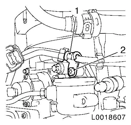
| 5. |
Detach bracket of MTA system high-pressure line (1)
|
|
|
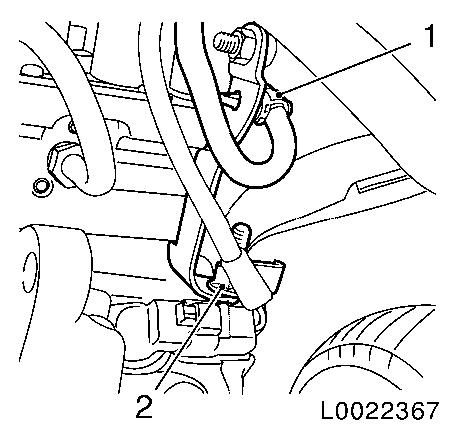
| 6. |
Release and disconnect wiring harness plug (2) of transmission
output speed sensor (1)
|
|
|
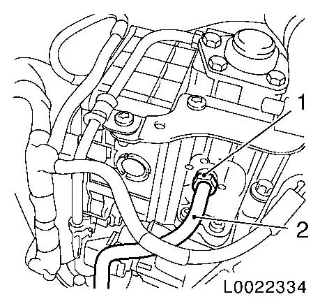
| 7. |
Detach high-pressure line (2) from gearshift module
|
|
|
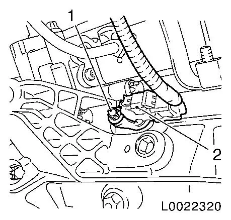
| 8. |
Detach gearshift module bracket at bottom of transmission
| • |
Unclip wiring harness (1)
|
|
|
|
| 9. |
Release gearshift module (2) at bottom
|
|

|
|
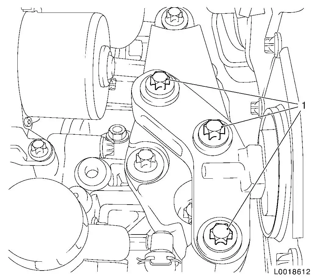
| 11. |
Detach left engine damping block from engine damping block
bracket
|
| 12. |
Lower engine with transmission using MKM-883-1-A
Note: Lower engine with
transmission until transmission is flush with front axle body.
Do not damage wiring harnesses and attaching parts
Pay attention to the vacuum line on the throttle valve module.
|
|
Important: Take care when
removing the gearshift module so as not to damage the pins of the
solenoid valve.
|
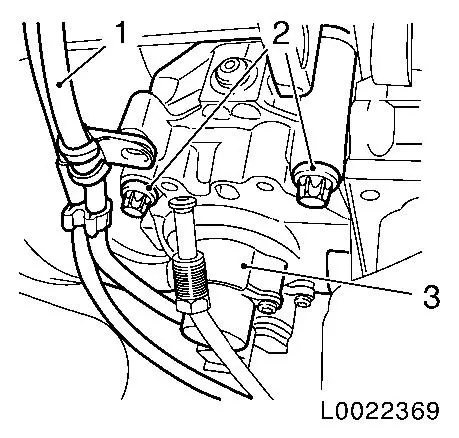
| 13. |
Remove gearshift module (3)
| • |
Remove MTA wiring harness and high-pressure line (1)
|
| • |
Remove gearshift module gasket
|
|
|
|
 Install
|
Important: Before installation of
the gearshift module, the transmission and gearshift module must be
checked to ensure they are in the correct installation position.
The transmission and gearshift module must be in the neutral ("N")
position.
|
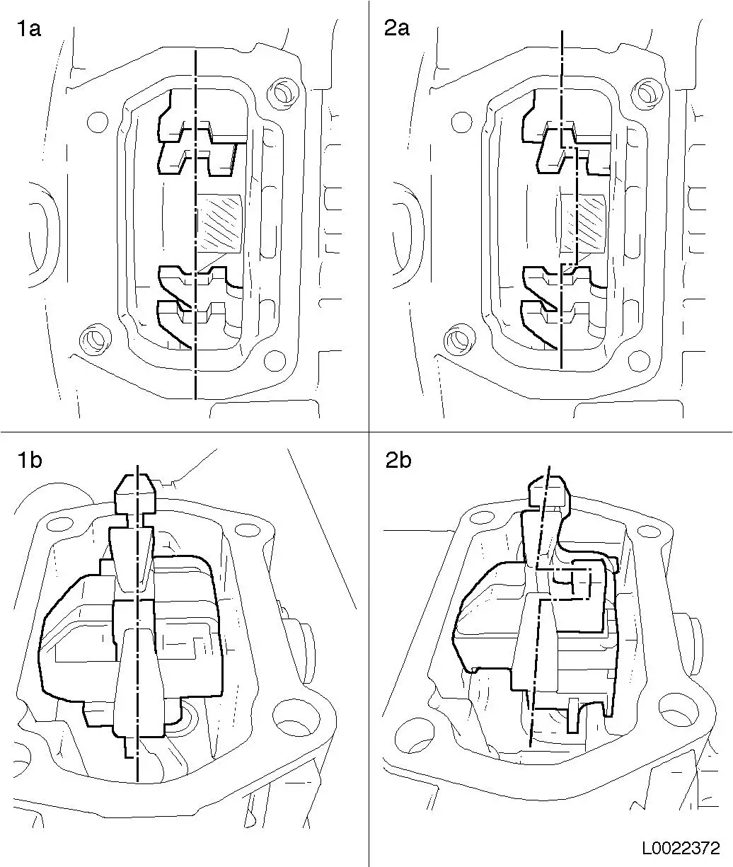
| 14. |
Check that transmission is in neutral position and move
gearshift finger to adjust as necessary
|
| 15. |
Check that gearshift module is in neutral position and adjust
by turning as necessary
|
|
| 16. |
Check that gearshift finger inclines to neutral position and
adjust through twisting as necessary
Note: 4 settings are
possible during this check. The two middle adjustment positions are
correct.
|
|
|
Important: Take care when
adjusting the gearshift module so as not to damage the pins of the
solenoid valve.
|
| 17. |
Install gearshift module (3)
| • |
Insert new gearshift module gasket
|
| • |
Insert MTA wiring harness and high-pressure line (1)
|
| • |
Tighten 2x bolt (2) 28 Nm
|
|
|
|
Important: Do not damage wiring
harnesses and attaching parts
Pay attention to the vacuum line on the throttle valve module.
|
| 18. |
Raise engine and transmission on the left hand side
|
|
| 19. |
Fasten left engine damping block
| • |
Tighten 3x bolt (1) 55 Nm
|
|
|
| 21. |
Fasten gearshift module (2) at bottom
| • |
Tighten 2x bolts (1) 28 Nm
|
|
|
|
| 22. |
Attach gearshift module bracket at transmission
| • |
Fasten stud bolt (2) 28 Nm
|
| • |
Clip in wiring harness (1)
|
|
|
|
| 23. |
Connect and lock wiring harness plug (2) of transmission output
speed sensor (1)
|
|
|
| 24. |
Connect and lock 2x wiring harness plugs
| • |
to shift position sensor (2)
|
| • |
to selector position sensor (1)
|
|
|
|
| 25. |
Fasten bracket of MTA system high-pressure line (1)
|
|
|
| 27. |
Install clutch module
|
Important: The electronic control
unit may only be removed and reinstalled once. If the electronic
control unit is removed again, it must be replaced.
|
| 28. |
Install electronic control unit
|
| 29. |
Fill CS Speed hydraulic fluid
Note: With the system
depressurised, fill the reservoir to just under the lower line of
the filler pipe.
|
| 30. |
Necessary Start-Up Routines for Easytronic
|
|
