Engine Control Module Wiring Harness Replacement (1.7L LPL,
LPV)
Removal Procedure
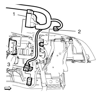
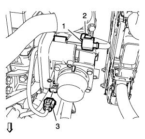
| 5. |
Disconnect the engine control
module wiring harness plug (1) and the glow plug controller wiring
harness plug (2). |
| 8. |
Disconnect the wiring harness
connection plug (3). |
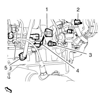
| 9. |
Disconnect and unclip the
heated oxygen sensor wiring harness plug (1). |
| 10. |
Disconnect the exhaust gas
recirculation regulating valve wiring harness plug (2) and the
exhaust temperature sensor wiring harness plug (3). |
| 11. |
Disconnect the crankshaft
position sensor wiring harness plug (5) and remove the ground cable
bolt (4). |
| 12. |
Disconnect the 2 fuel
injection pump wiring harness plugs (5, 6). |
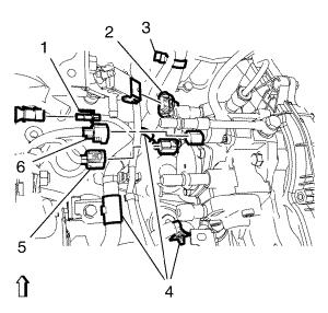
| 13. |
Disconnect the exhaust
pressure sensor wiring harness plug (2) and the engine oil pressure
indicator switch wiring harness plug (1). |
| 14. |
Unclip the 4 engine wiring
harness clips (3, 4) and hang the engine wiring harness
aside. |

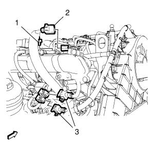
| 15. |
Disconnect the engine oil
level indicator switch wiring harness plug (3) and the generator
wiring harness plug (4). |
| 16. |
Disconnect the exhaust
temperature sensor wiring harness plug (2) and unclip the 2 engine
wiring harness clips (1). |
| 18. |
Disconnect the 2 exhaust gas
recirculation vacuum regulator solenoid valve wiring harness plugs
(3) and the turbocharger pressure sensor wiring harness plug
(2). |
| 19. |
Unclip the engine wiring
harness clip (1). |
| 20. |
Disconnect the throttle body
wiring harness plug (1) and the engine coolant temperature sensor
wiring harness plug (3). |
| 21. |
Unclip the engine wiring
harness clip (2). |
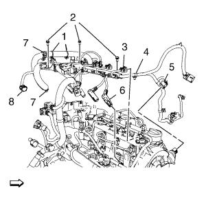
| 22. |
Disconnect the camshaft
position sensor wiring harness plug (5) and the fuel rail pressure
sensor wiring harness plug (8). |
| 23. |
Disconnect the 4 fuel injector
wiring harness plugs (3) and the 4 engine wiring harness glow plugs
(6). |
| 24. |
Remove the 3 engine wiring
harness bracket bolts (2). |
| 25. |
Unclip the 5 engine wiring
harness clips (1, 4 and 7). |
| 26. |
Remove the engine control
module wiring harness from the vehicle. |
Installation Procedure
| 1. |
Position the engine control
module wiring harness to the vehicle. |
| 2. |
Clip in 5 engine wiring
harness clips (1, 4 and 7). |
| 3. |
Install the 3 engine wiring
harness bracket bolts (2) and tighten to 10 N·m (89
lb in) . |
| 4. |
Connect the 4 fuel injector
wiring harness plugs (3) and the 4 engine wiring harness glow plugs
(6). |
| 5. |
Connect the camshaft position
sensor wiring harness plug (5) and the fuel rail pressure sensor
wiring harness plug (8). |
| 6. |
Clip in the engine wiring
harness clip (2). |
| 7. |
Connect the throttle body
wiring harness plug (1) and the engine coolant temperature sensor
wiring harness plug (3). |
| 8. |
Clip in the engine wiring
harness clip (1). |
| 9. |
Connect the 2 exhaust gas
recirculation vacuum regulator solenoid valve wiring harness plugs
(3) and the turbocharger pressure sensor wiring harness plug
(2). |
| 11. |
Connect the exhaust
temperature sensor wiring harness plug (2) and clip in the 2 engine
wiring harness clips (1). |
| 12. |
Connect the engine oil level
indicator switch wiring harness plug (3) and the generator wiring
harness plug (4). |
| 13. |
Position the engine wiring
harness. |
| 14. |
Clip in the 4 engine wiring
harness clips (3, 4). |
| 15. |
Connect the exhaust pressure
sensor wiring harness plug (2) and the engine oil pressure
indicator switch wiring harness plug (1). |
| 16. |
Connect the 2 fuel injection
pump wiring harness plugs (5, 6) to the fuel injection pump.
|
| 17. |
Connect the crankshaft
position sensor wiring harness plug (5) to the crankshaft position
sensor. |
| 18. |
Install the ground cable bolt
(4) and tighten to 25 N·m (18 lb ft)
. |
| 19. |
Connect the exhaust gas
recirculation regulating valve wiring harness plug (2) and the
exhaust temperature sensor wiring harness plug (3). |
| 20. |
Connect and clip in the heated
oxygen sensor wiring harness plug (1). |
| 21. |
Connect the wiring harness
connection plug (3). |
| 24. |
Connect the engine control
module wiring harness plug (1) and the glow plug controller wiring
harness plug (2). |
|
