Engine Control Module Wiring Harness Replacement (2.0L Diesel
LBS and LBX)
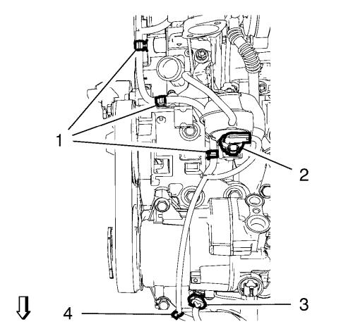
Removal Procedure
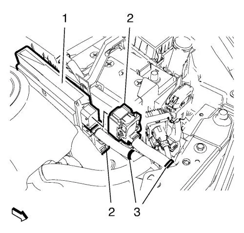
| 2. |
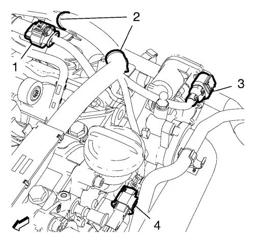
Disconnect the 2 engine
control module wiring harness plugs (2) from the engine control
module (1). |
| 3. |
Unclip the 2 wiring harness
clips (3). |
| 4. |
Remove the engine control
module bracket along with the engine control module in top
direction from the battery tray. |
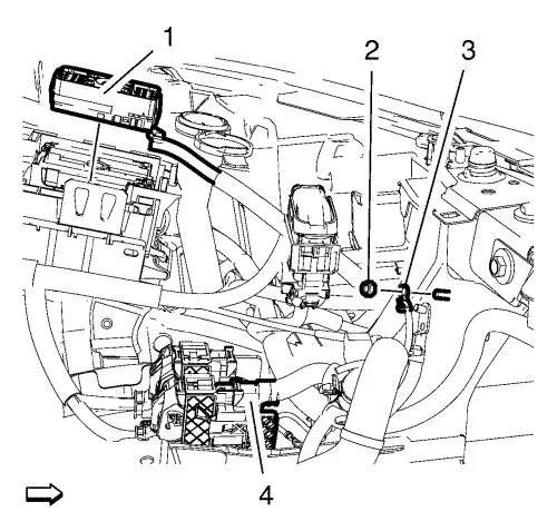
| 7. |
Remove the wiring harness
ground cable nut (2) and remove the wiring harness ground cable
(3). |
| 8. |
Remove the wiring harness plug
(1) in top direction from the front compartment fuse block
housing. |
| 9. |
Disconnect the wiring harness
connection adapter plug (4). |
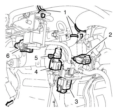
| 10. |
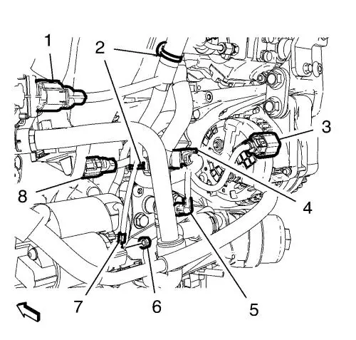
Disconnect the turbocharger
wastegate actuator valve wiring harness plug (6). |
| 11. |
Disconnect the heated oxygen
sensor wiring harness plug (3). |
| 12. |
Disconnect the exhaust
temperature sensor wiring harness plug (4). |
| 13. |
Disconnect the exhaust gas
recirculation vacuum regulator solenoid valve wiring harness plug
(2). |
| 14. |
Unclip the 4 wiring harness
clips (1, 5) from the brackets. |
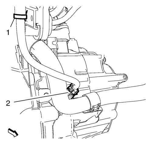
| 15. |
Disconnect the backup lamp
switch wiring harness plug (2) and unclip the wiring harness clip
(1) from the exhaust gas recirculation tank. |
| 16. |
Disconnect the engine coolant
temperature sensor wiring harness plug (4). |
| 17. |
Disconnect the throttle body
wiring harness plug (3). |
| 18. |
Disconnect the glow plug
connector wiring harness plug (1). |
| 19. |
Unclip the 2 wiring harness
clips (2) from the brackets. |
| 20. |
Disconnect the fuel injector
connector wiring harness plug (2). |
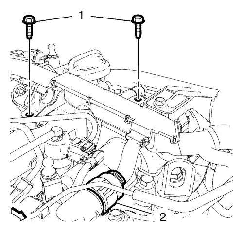
| 21. |
Remove the 2 wiring harness
conduit bolts (1). |
| 22. |
Disconnect the fuel rail
pressure regulator wiring harness plug (1). |
| 23. |
Disconnect the intake manifold
temperature sensor wiring harness plug (6). |
| 24. |
Disconnect the exhaust
pressure sensor wiring harness plug (5) and the fuel injection pump
wiring harness plug (4). |
| 25. |
Unclip the 5 wiring harness
clips (2, 3, 7). |
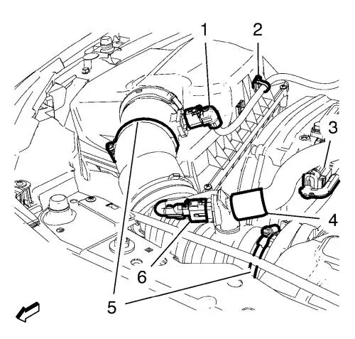
| 26. |
Disconnect the mass air flow
wiring harness plug (1) and unclip the wiring harness clip (2) from
the air cleaner assembly. |
| 27. |
Disconnect the camshaft
position sensor wiring harness plug (3) and the positive crankcase
ventilation heater wiring harness plug (6). |
| 28. |
Remove the positive crankcase
ventilation hose (4) from the positive crankcase ventilation
heater. |
| 29. |
Remove the 2 air cleaner
outlet duct clamps (5). |
| 30. |
Remove the air cleaner outlet
front duct and the air cleaner outlet rear duct. |
| 31. |
Disconnect the turbocharger
wastegate wiring harness plug (2). |
| 32. |
Unclip the 3 wiring harness
clips (1). |
| 35. |
If equipped with start/stop
system, disconnect the oil pressure valve wiring harness plug and
unclip the wiring harness clip from the engine block. |
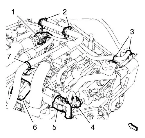
| 36. |
Disconnect the air
conditioning compressor wiring harness plug (3) and unclip the
wiring harness clip (4). Hang the wiring harness aside.
|
| 37. |
Remove the starter positive
cable nut (6) and the starter positive cable (7). |
| 38. |
Disconnect the oil pressure
switch wiring harness plug (5) and the generator wiring harness
plug (3). |
| 39. |
Disconnect the wiring harness
connector (4) from the wheel speed wiring harness. |
| 40. |
Disconnect the exhaust gas
recirculation valve wiring harness plug (1). |
| 41. |
Disconnect the intake manifold
runner actuator wiring harness plug (8) |
| 42. |
If equipped with start/stop
system, disconnect the auxiliary water pump wiring harness
plug. |
| 43. |
Unclip the 2 wiring harness
clips (2) from the brackets. Hang the wiring harness aside.
|
| 45. |
Remove the engine wiring
harness from the vehicle. |
Installation Procedure
| 1. |
Position the engine wiring
harness to the vehicle. |
| 3. |
Position the wiring harness.
Clip the 2 wiring harness clips (2) to the brackets. |
| 4. |
If equipped with start/stop
system, connect the auxiliary water pump wiring harness
plug. |
| 5. |
Connect the intake manifold
runner actuator wiring harness plug (8). |
| 6. |
Connect the exhaust gas
recirculation valve wiring harness plug (1). |
| 7. |
Connect the wiring harness
connector (4) to the wheel speed wiring harness. |
| 8. |
Connect the oil pressure
switch wiring harness plug (5) and the generator wiring harness
plug (3). |
| 9. |
Install the starter positive
cable (7) and the starter positive cable nut (6) and tighten to
5 N·m (44 lb in) . |
| 10. |
Position the wiring harness.
Connect the air conditioning compressor wiring harness plug (3) and
clip in the wiring harness clip (4). |
| 12. |
If equipped with start/stop
system, connect the oil pressure valve wiring harness plug and clip
the wiring harness clip to the engine block. |
| 14. |
Clip in the 3 wiring harness
clips (1). |
| 15. |
Connect the turbocharger
wastegate wiring harness plug (2). |
| 16. |
Install the air cleaner outlet
front duct and the air cleaner outlet rear duct. |
| 17. |
Install the 2 air cleaner
outlet duct clamps (5) and tighten. |
| 18. |
Install the positive crankcase
ventilation hose (4) to the positive crankcase ventilation
heater. |
| 19. |
Connect the camshaft position
sensor wiring harness plug (3) and the positive crankcase
ventilation heater wiring harness plug (6). |
| 20. |
Connect the mass air flow
wiring harness plug (1) and clip the wiring harness clip (2) to the
air cleaner assembly. |
| 21. |
Clip in the 5 wiring harness
clips (2, 3, 7). |
| 22. |
Connect the exhaust pressure
sensor wiring harness plug (5) and the fuel injection pump wiring
harness plug (4). |
| 23. |
Connect the intake manifold
temperature sensor wiring harness plug (6). |
| 24. |
Connect the fuel rail pressure
regulator wiring harness plug (1). |
| 25. |
Install the 2 wiring harness
conduit bolts (1) and tighten to 9 N·m (80 lb
in) . |
| 26. |
Connect the fuel injector
connector wiring harness plug (2). |
| 27. |
Clip the 2 wiring harness
clips (2) to the brackets. |
| 28. |
Connect the glow plug
connector wiring harness plug (1). |
| 29. |
Connect the throttle body
wiring harness plug (3). |
| 30. |
Connect the engine coolant
temperature sensor wiring harness plug (4). |
| 31. |
Connect the backup lamp switch
wiring harness plug (2) and clip the wiring harness clip (1) to the
exhaust gas recirculation tank. |
| 32. |
Clip the 4 wiring harness
clips (1, 5) to the brackets. |
| 33. |
Connect the exhaust gas
recirculation vacuum regulator solenoid valve wiring harness plug
(2). |
| 34. |
Connect the exhaust
temperature sensor wiring harness plug (4). |
| 35. |
Connect the heated oxygen
sensor wiring harness plug (3). |
| 36. |
Connect the turbocharger
wastegate actuator valve wiring harness plug (6). |
| 37. |
Connect the wiring harness
connection adapter plug (4). |
| 38. |
Install the wiring harness
plug (1) to the front compartment fuse block housing. |
| 39. |
Install the wiring harness
ground cable (3) and the wiring harness ground cable nut (2) and
tighten to 9 N·m (80 lb in) . |
| 42. |
Install the engine control
module bracket along with the engine control module to the battery
tray. |
| 43. |
Clip in the 2 wiring harness
clips (3). |
| 44. |
Connect the 2 engine control
module wiring harness plugs (2) to the engine control module
(1). |
|
