
Cylinder Head Cleaning and Inspection (Engine mechanics - 1.3L Diesel)
- Make
- Vauxhall
- Model
- Astra J
- Section
- Engine mechanics - 1.3L Diesel › Repair Instructions › Cylinder Head Cleaning and Inspection
‹ Prev Engine Mount Bracket InstallationNext › Fuel Injection Fuel Feed Pipe Installation - Fuel Rail to Fuel Injector
EngineCylinder Head Cleaning and Inspection
Cylinder Head Cleaning and InspectionSpecial Tools
For equivalent regional tools, refer to Special Tools . Cleaning Procedure
|
| 1. | Remove any old thread sealant, gasket material or sealant. |
| 2. | Clean all cylinder head surfaces with non-corrosive cleaning solvent. |
| Warning: Refer to
Safety Glasses Warning . |
| 3. | Blow out all the oil galleries using compressed air. |
| 4. | Remove any carbon deposits from the combustion chamber. |
Visual Inspection
| 1. | Inspect the cylinder head camshaft bearing surfaces for the following conditions: |
| • | Excessive scoring or pitting |
| • | Discoloration from overheating |
| • | Deformation from excessive wear |
| • | If the camshaft bearing journals appear to be scored or damaged, you must replace the cylinder head. DO NOT machine the camshaft bearing journals. |
| 2. | If any of the above conditions exist on the camshaft bearing surfaces, replace the cylinder head. |
| 3. | Inspect the cylinder head for the following: |
| • | Cracks, damage or pitting in the combustion chambers. |
| • | Debris in the oil galleries -- Continue to clean the galleries until all debris is removed. |
| • | Coolant leaks or damage to the deck face sealing surface -- If coolant leaks are present, measure the surface warpage as described under cylinder head measurement - deck flatness inspection. |
| • | Damage to any gasket surfaces. |
| • | Burnt or eroded areas in the combustion chamber. |
| • | Cracks in the exhaust ports and combustion chambers. |
| • | External cracks in the water passages. |
| • | Restrictions in the intake or exhaust passages. |
| • | Restrictions in the cooling system passages. |
| • | Rusted, damaged or leaking core plugs. |
| 4. | If the cylinder head is cracked or damaged, it must be replaced. No welding or patching of the cylinder head is allowed. |
Valve Inspection And Measurement
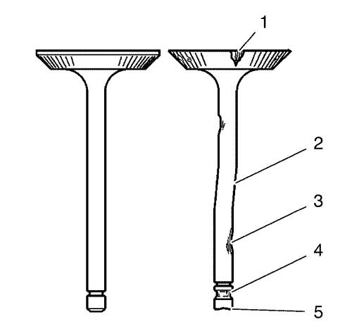
| 1. | Clean the valves of carbon and oil. Carbon can be removed with a wire brush. |
| 2. | Inspect the valves for the following conditions: |
| 2.1 | Inspect the valve faces for burning and cracking (1). If pieces are broken, replace the valve and inspect the corresponding piston and cylinder head area for damage. |
| 2.2 | Inspect the valve for straightness and distortion (2). Distorted valve must be replaced. |
| 2.3 | Inspect the valve stem for wear (3). |
| 2.4 | Inspect the valve key grooves for chipping and wear (4) and (5). Replace the valve if chipped or worn. |
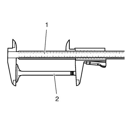
| 3. | Measure the valve length (2). Use a slide gauge (1). Refer to Engine Mechanical Specifications to find the permitted values. |
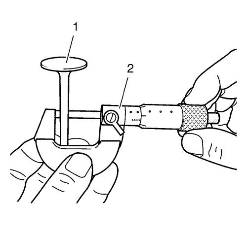
| 4. | Measure the valve stem diameter. Use a micrometer gauge (2). Refer to Engine Mechanical Specifications to find the permitted values. Note the measurement results. |
Cylinder Head Measurement
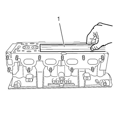
| 1. | Inspect the cylinder head sealing surface for flatness. Use a straightedge (1). |

| 2. | Prepare the gauge for valve stem to guide clearance measurement. Assemble the EN-6216 gauge and the EN-6216-200/300/400 gauge instruments as follows: |
| 2.1 | Install the extension (5) to the support (4). |
| 2.2 | Install the inside caliper (2) to the extension (5). |
| 2.3 | Install the gauge (3) to the support (4) and pretension to 1 mm (0.0394 in) . |
| 2.4 | Install the calibration washer (1) as shown to justify the gauge. |
| 2.5 | Adjust the gauge to 0 mm (0 in) by rotating the instrument dial. |
| 2.6 | Cautious remove the calibration washer (1). |
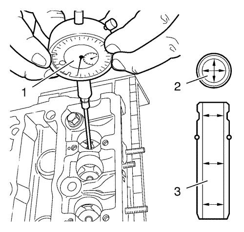
| 3. | Measure the valve guide inner diameter (2) as shown in different areas (3). Use the EN-6216 Gauge (1) and gauge instruments. Note the measurement results. Refer to Engine Mechanical Specifications to find the permitted values. |
| 4. | Substract the valve stem diameter from valve guide inner diameter to calculate the valve stem to guide clearance. Refer to Engine Mechanical Specifications to find the permitted values. |
| 5. | Turn the cylinder head upside down. |
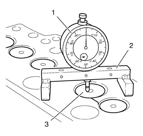
| 6. | Loosely install one valve to the cylinder head (3). |
| 7. | Place the EN-301 gauge bar (2) to the cylinder head sealing surface. |
| 8. | Install the EN-571-B gauge to the EN-301 gauge bar and measure the valve assembly height. Refer to Engine Mechanical Specifications to find the permitted values. |
‹ Prev Engine Mount Bracket InstallationNext › Fuel Injection Fuel Feed Pipe Installation - Fuel Rail to Fuel Injector
Parts & tools for this job For Vauxhall Astra
- PARTEngine gasket setSearch: Vauxhall Astra engine gasket set
- TOOLTorque wrenchSearch: 3/8 inch torque wrench
- TOOLFeeler gauge setSearch: feeler gauge set
Links open Amazon search results in a new tab. As an Amazon Associate I earn from qualifying purchases.