Piston, Connecting Rod, and Bearing Replacement
Special Tools
EN-470-B Torque Angle Sensor
For equivalent regional tools refer to
Special Tools .
Removal Procedure
|
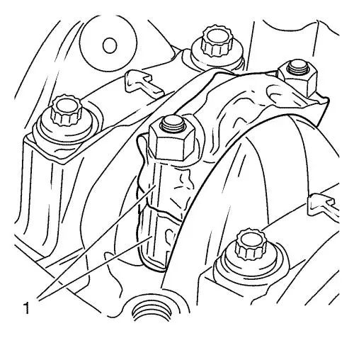
Note: The connecting
rod bearing caps must not be interchanged with other connecting
rods.
|
| 4. |
Mind the fracture face (1) of
connecting rod bearing cap and connecting rod. |
|
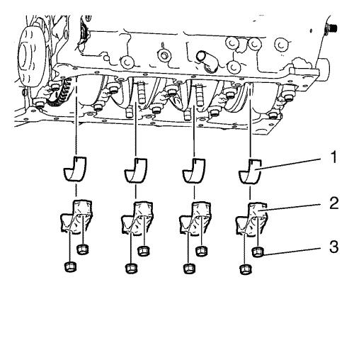
Note: Rotate the
crankshaft to a position where the connecting rod bearing nuts are
most accessible.
|
| |
Remove and DISCARD the 8 connecting rod bearing cap nuts
(3). |
| 5. |
Remove the connecting rod
bearing caps (2). |
| 6. |
Remove the lower connecting
rod bearings (1). |
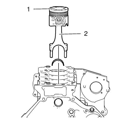
| 7. |
Remove the 4 pistons (1) in
compound with the 4 connecting rods (2) from the cylinder
block. |
Installation Procedure
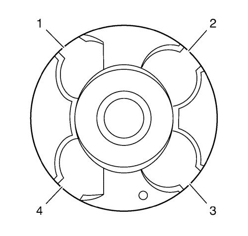
| 1. |
Adjust the piston ring joint
as shown. Dislocate the piston rings 90° to
each other. |
| 2. |
Install a piston ring
compressor in order to compress the piston rings. |
|
Note: Lubricate the
pistons, the cylinder bore and the piston ring compressor with
engine oil.
|
| 3. |
Install the pistons (1) in
compound with the connecting rods (2). |
|
Note: The marks on
piston heads and connecting rods must point to the timing side.
|
| 4. |
Push the pistons down to the
cylinder bore. |
| 5. |
Lubricate the connecting rod
bearings and the connecting rod bearing caps with engine
oil. |
| 6. |
Install the upper connecting
rod bearings, the lower connecting rod bearings (1) and the
connecting rod bearing caps (2). |
|
Note: Mind the
fracture faces (1) of connecting rod bearing caps and connecting
rods. Examine that the connecting rod bearing caps are installed in
their original position.
|
| 7. |
Install the 8 NEW connecting
rod bearing cap nuts in the following order: |
| |
7.1 |
Tighten the nuts to 25
N·m (18 lb ft) . |
| |
7.2 |
Tighten the nuts to an
additional 100° . Use EN-470-B
angle sensor . |
| |
7.3 |
Tighten the nuts to an
additional 15° . Use EN-470-B
angle sensor . |
|
