Stabilizer Shaft Replacement
Special Tools
| • |
CH 49289
Centering Frame |
For equivalent regional tools, refer to
Special Tools .
Removal Procedure
| 1. |
Turn the front wheels to the
straight forward position and secure the steering wheel from
moving. |
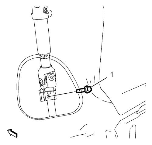
| 2. |
Remove the lower steering
intermediate shaft bolt (1). |
| 3. |
Remove the steering
intermediate shaft from the steering gear. |
| 9. |
Remove and DISCARD lower
stabilizer link shaft nut (2) on both sides. |
| 10. |
Remove stabilizer link shaft
(1) from stabilizer shaft on both sides. |
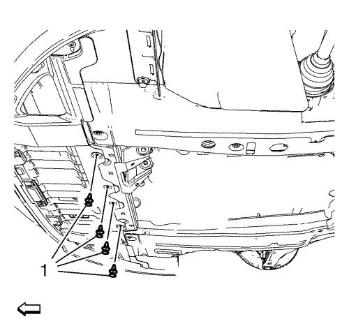
| 11. |
Remove 4 fasteners (1) of
engine side cover on both sides. |
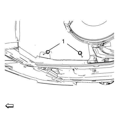
| 12. |
Remove 4 fasteners (1) of
front engine compartment cover. |
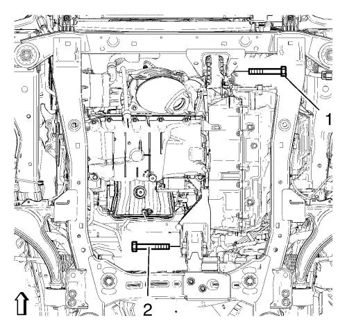
| 13. |
Remove the front (1) and the
rear (2) transmission mount bracket bolts. |
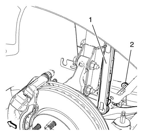
| 14. |
Remove 2 rear suspension frame
bolts (2). |
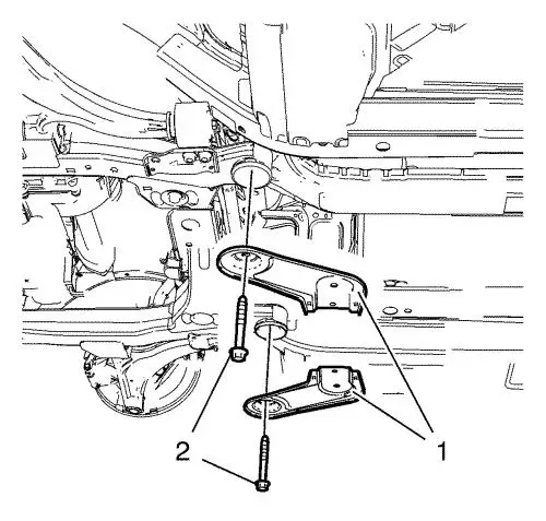
| |
Remove rear frame reinforcements (1). |
|
Note: The SPX
installation manual is supplied with the special tool and is also
available online from SPX directly. Go to
www.spxtools-shop.com.
|
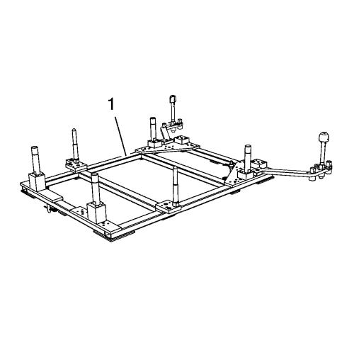
| 15. |
Assemble the CH-49289
centering frame (1) according to the details provided in the
SPX installation manual. |
| 16. |
Support the CH-904
base frame on a jack. |
| 17. |
Support the CH-49289
centring frame on the CH-904 base frame
. |
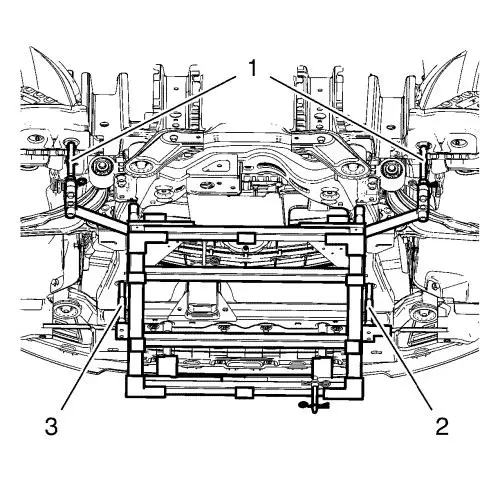
|
Note: Positioning
pins (2, 3) of CH-49289 adapter MUST stick into
holes of suspension frame. The SPX installation manual is supplied
with the special tool and is also available online from SPX
directly. Go to www.spxtools-shop.com.
|
| 18. |
Install the CH-49289
centring frame according to the details provided in the SPX
installation manual. |
| 19. |
Check if wheel alignment is
required. Move out position pins (1) and try to insert into
underbody holes. If guide pins can NOT be inserted, the
Wheel Alignment Measurement is required after installation of
the suspension frame. |
| 20. |
Lower the front suspension
frame assembly enough to gain access to the stabilizer shaft
insulator bolts. Bent engine side cover aside. |
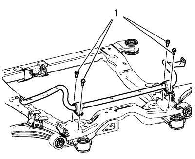
| 21. |
Remove and DISCARD the 4 front
stabilizer shaft insulator clamp bolts (1). |
|
Note: The stabilizer
shaft insulator is serviced with the stabilizer shaft. It is NOT
serviced separately.
|
| 22. |
Remove the stabilizer
shaft. |
Installation Procedure
| 1. |
Install the stabilizer
shaft. |
| 2. |
Install the 4 NEW front
stabilizer shaft insulator clamp bolts (1). Tighten the stabilizer
shaft bolts a first pass to 22 N·m (16 lb
ft) . |
| 3. |
Tighten the 4 NEW front
stabiliser shaft insulator clamp bolts (1) a final pass to
plus 30 degrees , using the EN-45059
angle meter . |
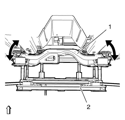
| 4. |
Raise the frame (1) carefully,
using CH 49289 centering frame (2). |
|
Note: Positioning
pins (1) of CH-49289 centring frame MUST be
extended to guide into underbody holes.
|
| 5. |
Remove the CH-49289
centring frame according to the details provided in the SPX
installation manual. |
|
Note: The SPX
installation manual is supplied with the special tool and is also
available online from SPX directly. Go to
www.spxtools-shop.com.
|
| 6. |
Remove the CH-49289
centring frame from the CH-904 base frame
. |
| 7. |
Remove the CH-904
base frame from the jack. |
| 8. |
Disassemble the
CH-49289 centering frame (1) according to the
details provided in the SPX installation manual. |
| 9. |
Install the 2 frame
reinforcements (1). |
| 10. |
Install the 2 frame rear bolts
(2) and tighten to 160 N·m (118 lb ft)
. |
| 11. |
Install the front transmission
mount bolt (1) and tighten to 58 N·m (43 lb
ft) . |
| 12. |
Install the rear transmission
mount bracket bolt (2) and tighten to 100 N·m (74 lb
ft) . |
| 13. |
Install and tighten 4
fasteners (1) of engine side cover on both sides. |
| 14. |
Install and tighten 4
fasteners (1) of front engine compartment cover. |
| 18. |
Install and tighten NEW lower
stabilizer link shaft nut (2) on both sides to 65
N·m (48 lb ft) . |
|
