|
Repair engine using a short-block
Warning: When
working on the common rail system, wait one minute after switching
off the engine. The system relieves the pressure itself.
Important:
Cleanliness is absolutely essential when working on the fuel system
because even small dirt particles can lead to disruption of engine
operation or the fuel system. On opening fuel system connectors,
seal them with appropriate sealing plugs
1) . Sealing plugs are only designed to be used once.
 Remove Remove
| 2. |
Detach manual transmission from engine 
|
| 3. |
Remove starter
| • |
Detach 2 wiring harnesses
|
|
|
|
| 4. |
Remove thrust plate and clutch disc
|
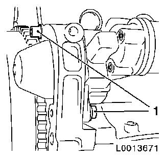
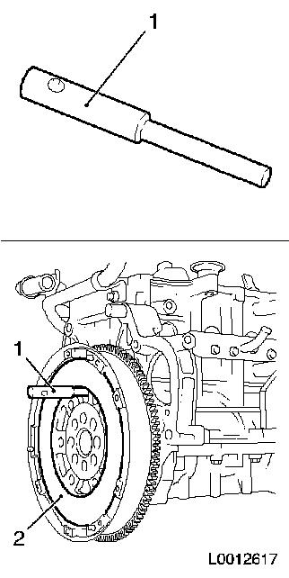
| 5. |
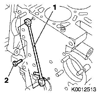
Lock crankshaft
| • |
Insert EN-46778 (1) into cylinder
block through flywheel (2)
|
|
|
|
| 6. |
Place collecting basin underneath.
|
| 7. |
Drain engine oil
| • |
Tighten drain bolt 20 Nm
|
|
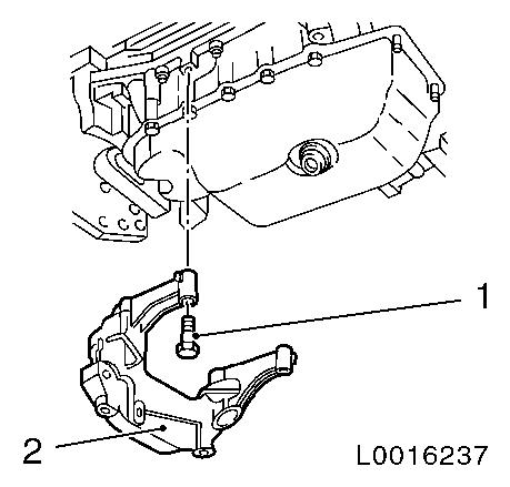
| 9. |
Detach transmission bracket (2)
| • |
Detach cylinder block from base plate
| – |
Unscrew 4x bolt (1)
Note: Note differing
bolt lengths!
|
|
|
|
|
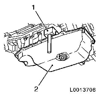
| 10. |
Remove oil pan (2)
| • |
Unscrew 2 nuts
Note: Carefully
separate oil pan (2) from base plate using KM-J-37228 (1)
|
|
|
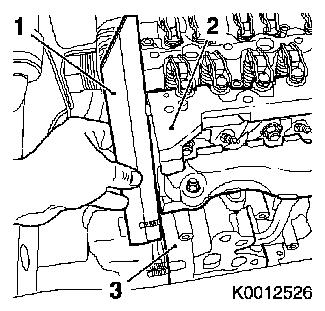
|
| 12. |
Detach wiring harness on engine intake side
| • |
Disconnect 4x wiring harness plug, injector
|
| • |
Disconnect 4x sheathed glow plug wiring harness plugs
|
| • |
Disconnect camshaft sensor wiring harness plug
|
| • |
Disconnect crankshaft sensor wiring harness plug
|
| • |
Disconnect wiring harness plug of coolant temperature
sensor
|
|
| 13. |
Disconnect wiring harness on engine exhaust side
| • |
Disconnect common-rail pressure sensor wiring harness plug
|
| • |
Disconnect boost pressure sensor wiring harness plug
|
| • |
Disconnect common-rail pressure regulator wiring harness
plug
|
| • |
Disconnect EGR valve wiring harness plug
|
|
| 14. |
Disconnect engine wiring harness
| • |
Unclip 2 harnesses from bracket
|
|
| 15. |
Place collecting basin underneath.
|
Important: After disconnecting
the pressure lines, seal the openings of the injectors,
high-pressure pump and accumulator with protective caps (these can
be ordered from the Opel parts catalogue, catalogue no. 45 06 154 /
part no. 92 01 697)
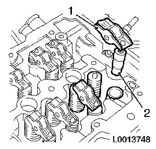
|
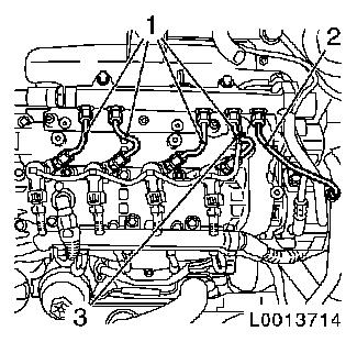
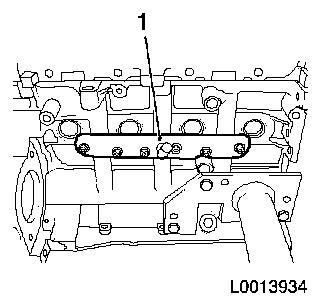
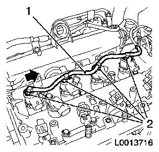
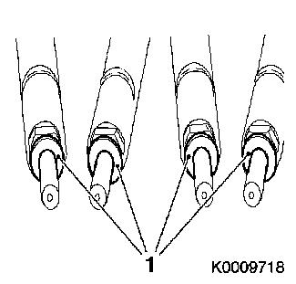
| 16. |
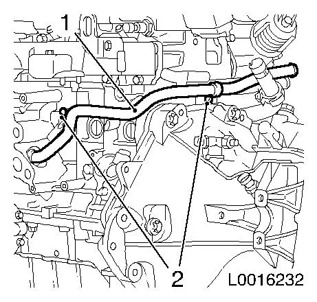
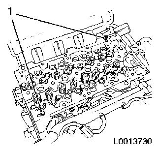
Remove high-pressure lines
| • |
Detach 4 accumulator high pressure lines (1) at injectors
|
| • |
Detach high pressure pump line (2) at accumulator
|
| • |
Unclip leak oil line (3)
|
|
|
|
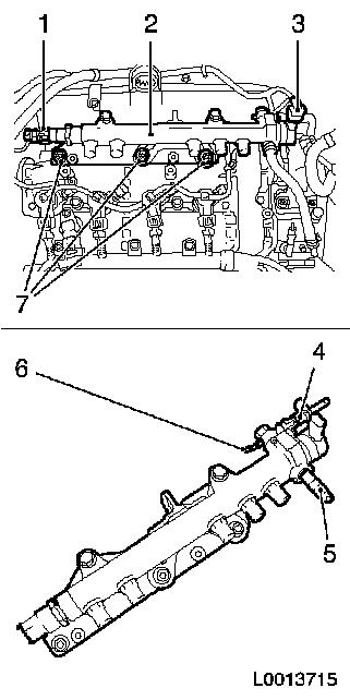
| 17. |
Detach accumulator (2) with bracket
| • |
Disconnect 2 wiring harness plugs (1) and (3)
|
| • |
Detach fuel return line from high-pressure pump to accumulator
at connection (5)
|
| • |
Detach oil leak line from connection (6)
|
| • |
Unscrew 3x bolt (7)
Note: Remove engine
transport shackle
|
| • |
Detach fuel return line from connection (4)
| – |
Disconnect quick-release coupling with KM-796-A
|
|
|
|
|
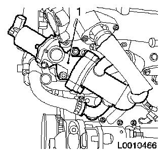
| 18. |
Detach exhaust gas recirculation valve (1) with radiator
EGR
| • |
Detach exhaust gas recirculation pipe from intake manifold
|
| • |
Detach coolant hose from thermostat housing
|
|
|
|
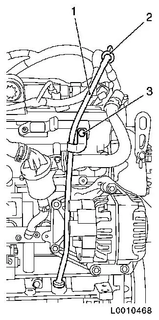
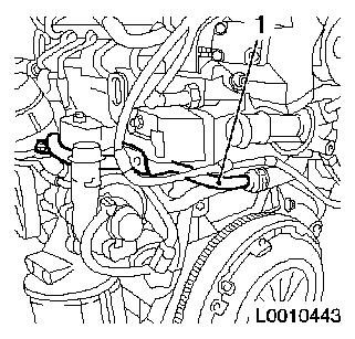
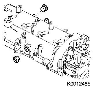
| 19. |
Detach oil dipstick guide tube (1) with oil dipstick (2)
|
|
|
| 20. |
Detach engine vent oil separator (1)
| • |
Detach engine vent hose from timing case
|
| • |
Detach engine vent hose from flange
|
|
|
|
| 21. |
Detach cylinder block ventilation exhaust connector (1)
|
|
|
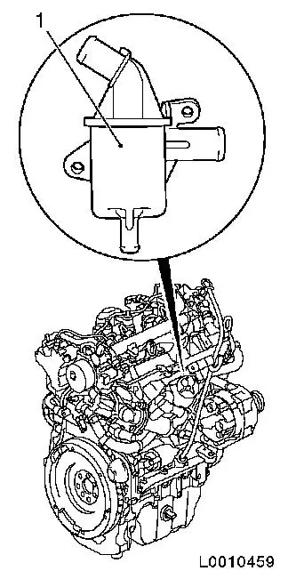
| 22. |
Remove fuel distributor pipe (1)
| • |
Detach from heat exchanger
|
| • |
Detach from cylinder block
|
| • |
Unclip 2 wiring harnesses
|
|
|
|
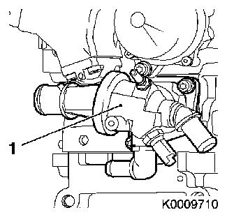
| 23. |
Detach thermostat housing (1) from cylinder head
|
|
|
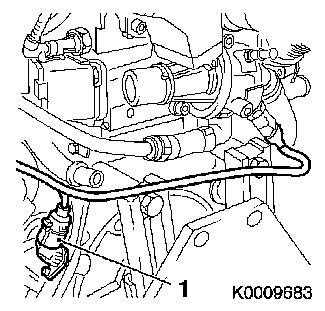
| 24. |
Remove coolant pipe (1)
|
|
|
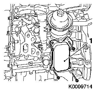
| 25. |
Detach oil filter housing (1)
|
|
|
| 26. |
Remove crankshaft sensor (1)
|
|
|
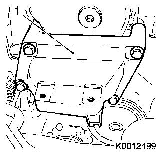
| 27. |
Detach right-hand engine damping block adapter (1)
|
|
|
| 28. |
Remove ribbed V-belt tensioner
|
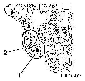
| 29. |
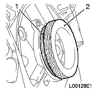
Remove torsional vibration damper (1)
| • |
Unscrew 4 bolts
Note: Counterhold at
torsional vibration damper flange bolt (2)
|
|
|
|
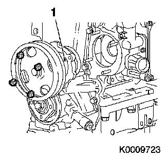
| 30. |
Remove coolant pump (1)
|
|
|
| 31. |
Detach torsional vibration damper flange
Note: Left hand
thread
| • |
Remove bolt (1)
| – |
Counterhold with KM-662-C (2)
|
|
|
|
|
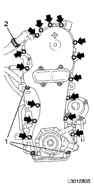
| 32. |
Remove timing case
| • |
Detach engine vent hose (2) from timing case
|
| • |
Unscrew 15x bolts (arrows)
|
|
|
|
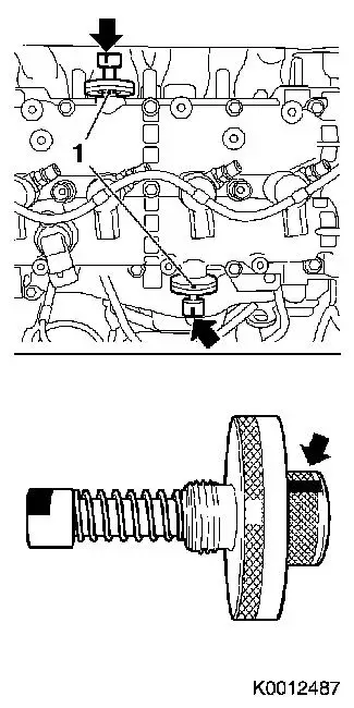
| 33. |
Remove 2 closure bolts from camshaft housing
|
|
|
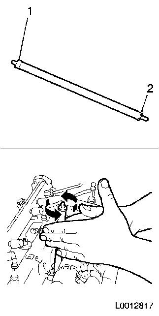
| 35. |
Lock camshafts
| • |
Screw in 2 camshaft reference drifts EN-46781 (1)
|
| • |
Check for proper installation position
Note: The fixing
reference drift must be fitted in a horizontal position. Put guide
marks on the reference drifts (arrows).
|
| • |
Turn the camshaft back and forth at camshaft drive pinion bolt
until EN-46781 engages in both
camshafts
|
|
|
|
| 36. |
Remove timing chain tensioner
| • |
Tighten timing chain tensioner. Lock in pretensioned position
using KM-955
|
|
|
|
| 37. |
Detach timing chain tension rail
|
| 38. |
Detach timing chain sliding rail
|
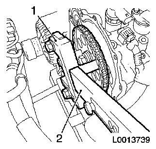
| 39. |
Undo camshaft drive gear
| • |
Counterhold at camshaft drive gear with KM-6347 (1) and KM-956-1
(2)
|
|
|
|
| 40. |
Remove timing chain with camshaft drive gear and crankshaft
drive gear
|
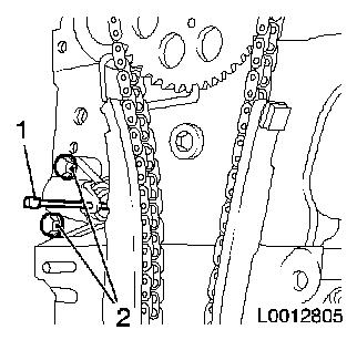
| 41. |
Detach timing chain oil spray nozzle (1)
|
|
|
| 42. |
Detach oil leak line (1)
| • |
Disengage 4 clamps (2) in direction of arrow
|
|
|
|
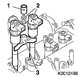
| 43. |
Detach injectors
| • |
Remove 2 injector brackets (3)
| – |
Unscrew 2 nuts (1)
Note: The injectors (2)
can only be removed in pairs with the bracket (cylinders 1 and 2 or
cylinders 3 and 4)
|
|
|
|
|
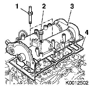
| 44. |
Remove camshaft housing (3)
| • |
Unscrew 16x bolt (2)
Note: Note differing
bolt lengths!
|
| • |
Unscrew and remove 2x stud bolt (1)
|
|
|
|
| 45. |
Remove 16 roller cam followers (1) with hydraulic valve lifters
(2)
Note: Put down in order
of removal
|
|
|
| 46. |
Remove 2 x camshaft housing centring pins (1)
|
|
|
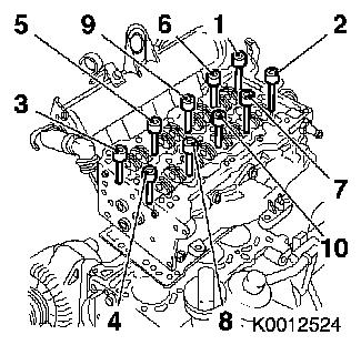
| 47. |
Loosen cylinder head
| • |
Unscrew 10 bolts
Note: Undo bolts in
order shown
|
|
|
|
| 48. |
Remove cylinder head
Note: Second person
required
|
| 51. |
Reassemble short-block
|
| 52. |
Clean parts and sealing surfaces
|
 Install
| 53. |
Drive guide sleeves into cylinder block
| • |
4 guide bushings, using KM-427
|
|
|
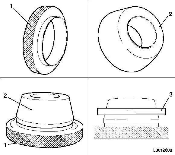
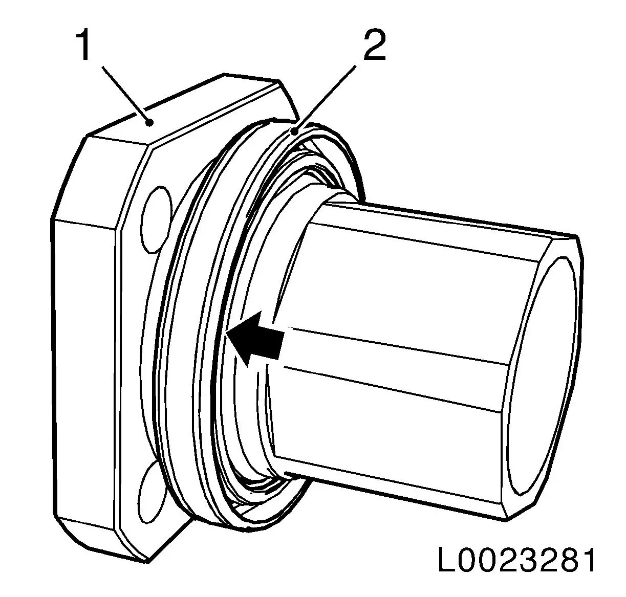
| 54. |
Push rear crankshaft seal ring onto EN-46777-10
| • |
Push on EN-46777-10 (1)
Note: Coat crankshaft
seal ring with silicone grease (white)
|
| • |
Slide crankshaft seal ring (3) over EN-46777-10
|
|
|
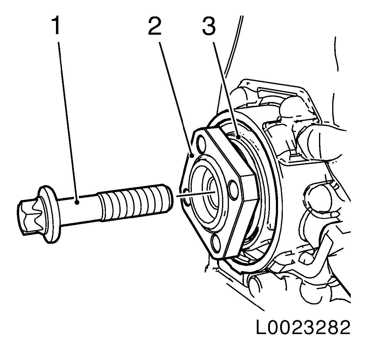
| 55. |
Install rear crankshaft seal ring (1) with EN-46777-10 (2)
|
|
|
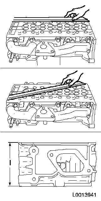
| 57. |
Check cylinder head for plane surface
| • |
Use straight edge and feeler gauge to check length and breadth
of cylinder block sealing surfaces for torsion
|
|
|
|
| 58. |
Set cylinder 1 to TDC
| • |
Insert MKM-571-B in KM-301
|
| • |
Place KM-301 with MKM-571-B in position on cylinder block
|
| • |
Place probe of MKM-571-B on piston
head
|
| • |
Turn engine in its direction of rotation
Note: Determine highest
point of cylinder 1 by turning the crankshaft.
|
|
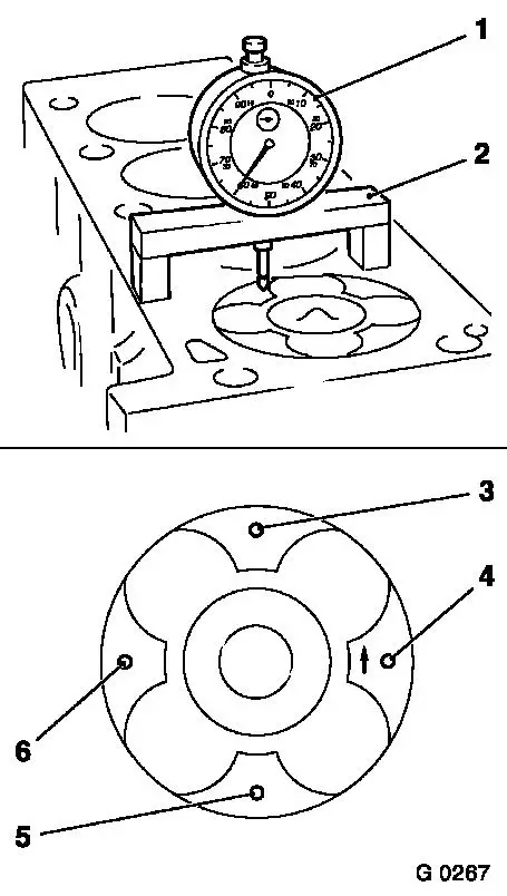
| 59. |
Measure piston projection
| • |
Place probe of MKM-571-B in position
on cylinder block
|
| • |
Set dial to zero
Note: Note
pretension.
| – |
Determine high point by turning crankshaft
|
|
| • |
Measure piston projection
| – |
Measure on all 4 pistons
|
| – |
Carry out measurement on two different locations (3 and 4) or
(5 and 6)
|
|
|
|
|
| 60. |
Lock crankshaft
| • |
Insert EN-46778 (1) into cylinder
block through flywheel (2)
|
|
|
|
| 61. |
Check cylinder head for plane surface
| • |
Use straight edge and feeler gauge to check length and breadth
of cylinder head sealing surfaces for torsion
|
| • |
Maximum deflection is 0,10 mm
|
|
| 62. |
Measure the height of the cylinder head
| • |
Sealing surface to sealing surface
|
| • |
Dimension l: = 105.45 –105.55
mm
|
|
|
|
Important: The largest piston
projection found determines the selection of the cylinder head
gasket with appropriate identification.
|
| 63. |
Replace cylinder head gasket
| • |
Lay cylinder head gasket in place
|
Piston projection
|
Thickness of cylinder head gasket
|
Code
|
|
0.028 - 0.127 mm
|
0.67 - 0.77 mm
|
no hole
|
|
0.128 - 0.227 mm
|
0.77 - 0.87 mm
|
one hole
|
|
0.228 - 0.327 mm
|
0.87 - 0.97 mm
|
two holes
|
Note: Note guide
bushings.
|
|
| 64. |
Insert cylinder head
Note: Second person
required
|
| 65. |
Screw in 10x cylinder head bolt
| • |
Use new bolts
Note: Do not tighten
bolts.
|
|
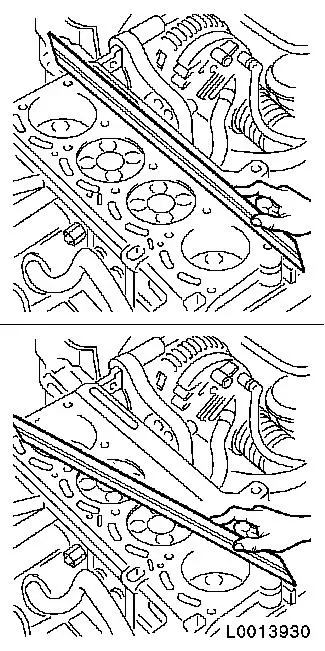
| 66. |
Align cylinder head
| • |
Use straight edge to align cylinder head (2) with cylinder
block (3)
|
|
|
|
| 67. |
Fasten cylinder head
| • |
Tighten 10 cylinder head bolts 40 Nm +
90°+ 90°
Note: Note tightening
sequence.
|
|
|
|
| 68. |
Insert 16x roller cam follower
Note: Note the
dismantling sequence.
|
| 69. |
Insert camshaft housing
| • |
Insert new gasket
Note: Note marking
("TOP")
|
| • |
Screw in 2 stay-bolts (M8)
|
|
| 70. |
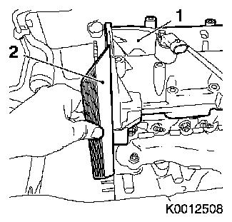
Align camshaft housing (1)
| • |
Using straight edge (2), align with cylinder head
|
|
|
|
|
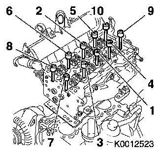
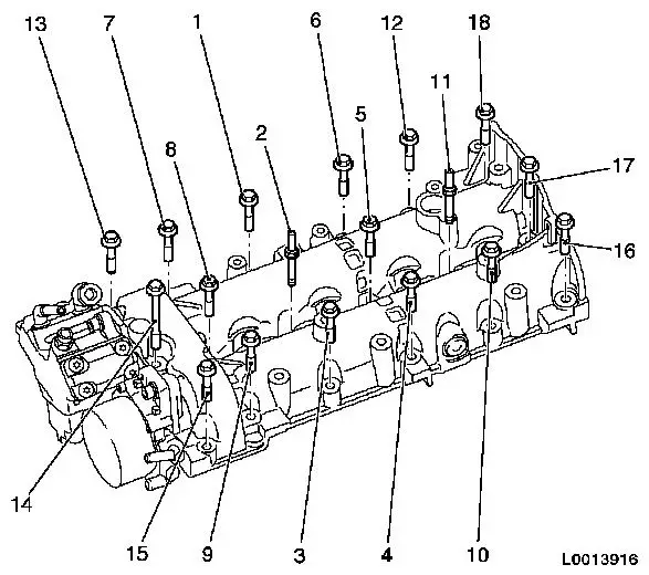
| 71. |
Tighten camshaft housing
| • |
Tighten 2 stay-bolts (M8) (2) and (11) 25 Nm
|
| • |
Tighten 16 (M7) bolts 18 Nm
Note: Note longer bolt
(14). Comply with tightening sequence.
|
|
|
| 72. |
Clean 4 injector seats with EN-47632
| • |
Loosen dirt with brush side (1)
|
| • |
Remove dirt with sponge side (2)
|
|
|
|
| 73. |
Install 4 injectors
| • |
Fit 4 new seal rings to injector shaft
|
| • |
Replace 4 injector seal rings (1)
|
|
|
|
| 74. |
Attach oil leak line
| • |
Disengage 4 retaining clamps
|
|
| 75. |
Attach timing chain oil spray nozzle
|
| 76. |
Attach timing chain guide rail
|
| 77. |
Insert timing chain with camshaft drive gear and crankshaft
drive gear
|
| 78. |
Fasten camshaft drive gear
| • |
Counterhold at camshaft drive gear with KM-6347 and KM-956-1
|
|
| 79. |
Attach timing chain tension rail
|
| 80. |
Attach timing chain tensioner
| • |
Tension timing chain tensioner
|
|
|
Important: The timing case must
be installed within 10 minutes of applying the silicone
sealant.
|
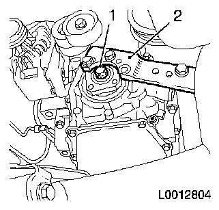
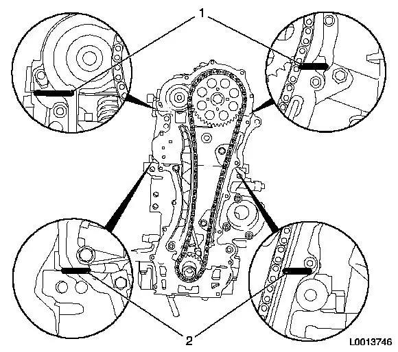
| 81. |
Insert timing case gasket
| • |
Apply silicone sealant (grey) to the transitions between the
cylinder head and camshaft housing (1) and the cylinder block and
cylinder head (2)
|
|
|
| 82. |
Attach timing case.
| • |
Centre timing case with EN-46775
(1)
|
| • |
Attach engine vent hose to timing case
|
|
|
|
| 83. |
Push crankshaft seal ring front (2) onto seal ring flange
torsional vibration damper (1).
|
|
|
| 84. |
Install flange torsional vibration damper (2) with front
crankshaft seal ring (1).
| • |
Carefully tighten bolt to crankshaft stop.
|
| • |
Remove torsional vibration damper flange.
|
|
|
|
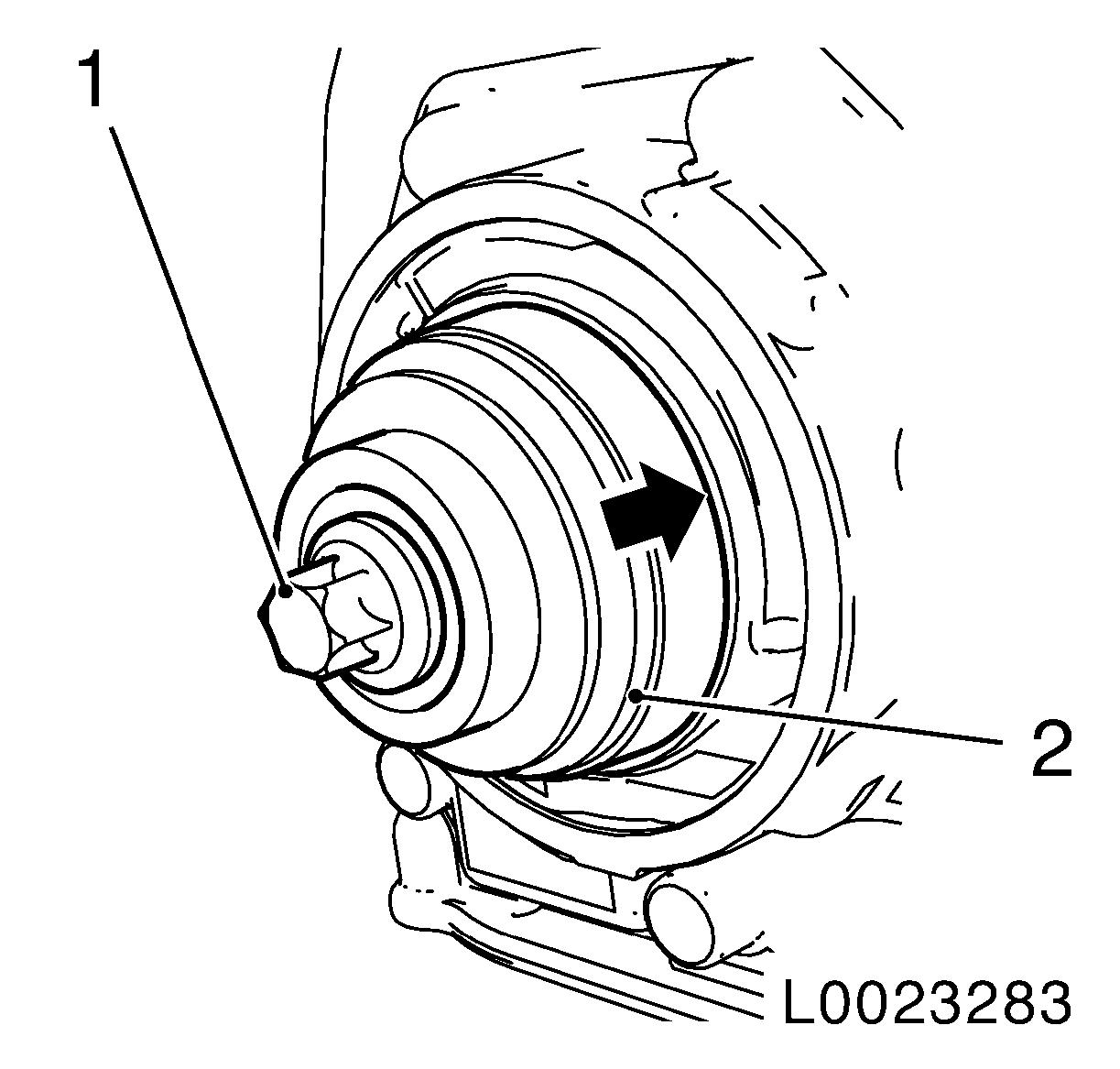
| 85. |
Press in seal ring with flat side of EN-46775 (2)
| • |
Tighten bolt (1) carefully until EN-46775 lies on timing case (arrow).
|
|
|
|
| 87. |
Attach torsional vibration damper flange
Note: Left hand
thread
| • |
Tighten bolt 50 Nm + 90°
| – |
Counterhold using KM-662-C
|
|
|
| 89. |
Check camshaft timing
| • |
Unscrew 2 camshaft reference drifts EN-46781
|
| • |
Turn engine 690° in
direction of engine rotation at torsional vibration damper flange
bolt
|
| • |
Screw in 2 camshaft reference drifts EN-46781
|
| • |
Turn engine in direction of engine rotation at torsional
vibration damper flange bolt until reference drift EN-46781 engages audibly in both camshafts
|
|
| 90. |
Check position of crankshaft by inserting EN-46778 through hole in flywheel
| • |
Turn crankshaft in direction of engine rotation at torsional
vibration damper flange bolt until EN-46778 engages in cylinder block
Note: If EN-46778 cannot be inserted in cylinder block, repeat
the adjustment process
|
|
| 91. |
Unscrew 2 camshaft reference drifts EN-46781
|
| 92. |
Insert 2 closure bolts
Note: Complete assembly
operations within 10 minutes
| • |
Coat 2 bolts with locking compound (red)
|
| • |
Tighten 2 closure bolts 15 Nm
|
|
| 93. |
Install torsional vibration damper
|
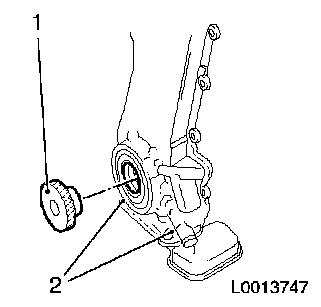
| 94. |
Attach coolant pump
Note: Use new gasket
and coat it with silicone grease (white). The coolant pump journal
must point to the filler port.
|
| 95. |
Attach ribbed V-belt tensioner
|
| 96. |
Attach right engine damping block adapter
|
| 97. |
Install crankshaft sensor
|
| 98. |
Install oil filter housing
| • |
Use new gasket
Note: Note differing
bolt lengths!
|
|
| 99. |
Attach coolant pipe to cylinder block
Note: Use new gasket
and coat it with silicone grease (white)
|
| 100. |
Attach thermostat housing to cylinder head
| • |
Use new gasket
Note: Coat seal ring
with silicone grease (white)
|
|
| 101. |
Attach thermostat housing coolant pipe to oil filter
housing
Note: Use new
gasket
| • |
Attach coolant hose to thermostat housing
|
| • |
Attach to oil filter housing
|
| • |
Attach to cylinder block
|
|
| 102. |
Attach cylinder block ventilation exhaust connector
|
| 103. |
Attach engine vent oil separator
| • |
Attach engine vent hose to timing case
|
| • |
Attach engine vent hose to flange
|
|
| 104. |
Install oil dipstick guide tube
|
| 105. |
Attach exhaust gas recirculation valve with radiator EGR
| • |
Attach exhaust gas recirculation pipe to intake manifold
|
| • |
Attach coolant hose to thermostat housing
|
|
| 106. |
Attach accumulator with bracket
| • |
Tighten 3 bolts 25 Nm
Note: Insert engine
transport shackle
|
| • |
Attach fuel return line to high pressure pump
|
| • |
Attach fuel return line
| – |
Close quick-release fitting
|
|
| • |
Connect 2 wiring harness plugs
|
|
| 107. |
Attach high pressure lines
| • |
Use new high pressure lines
|
| • |
Attach 4 accumulator high pressure lines to injectors
| – |
Tighten 4 union nuts (M12) 24 Nm
|
| – |
Tighten 4 union nuts M14 28 Nm
|
|
| • |
Attach high pressure pump line to accumulator
| – |
Tighten union nut M12 24 Nm
|
| – |
Tighten union nut M14 28 Nm
|
|
|
| 108. |
Attach fuel supply line
| • |
Attach fuel line to high pressure pump
|
| • |
Tighten 3 bolts
Note: Take care to
avoid the 2 ground cables.
|
| • |
Clip vacuum line into bracket
|
|
| 109. |
Connect engine wiring harness
| • |
Clip in bracket (twice)
|
|
| 110. |
Connect wiring harness on engine exhaust side
| • |
Connect wiring harness plug of common-rail pressure sensor
|
| • |
Connect wiring harness plug of boost pressure sensor
|
| • |
Connect wiring harness plug of common rail pressure
regulator
|
| • |
Connect EGR valve wiring harness plug
|
|
| 111. |
Attach wiring harness on engine intake side
| • |
Connect 4 injector wiring harness plugs
|
| • |
Connect 4 glow plug wiring harness plugs
|
| • |
Connect camshaft sensor wiring harness plug
|
| • |
Connect wiring harness plug of crankshaft sensor
|
| • |
Connect wiring harness plug of coolant temperature sensor
|
|
| 113. |
Unscrew 2 stay-bolts from timing cover
Note: Replace
stay-bolts with bolts when attaching the oil pan
|
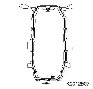
| 114. |
Apply sealing compound
Note: Apply a bead of
silicone sealant (grey) to the oil pan sealing surface
|
|
|
Important: The oil pan must be
installed within 10 minutes of applying the silicone sealant.
|
| 115. |
Attach oil pan
| • |
To cylinder block base plate
|
| • |
Connect wiring harness plug of engine oil level sensor
|
|
| 116. |
Attach transmission bracket
| • |
To cylinder block base plate
|
| • |
On transmission
Note: Note differing
bolt lengths!
|
|
| 118. |
Top up and correct engine oil level
| • |
Use prescribed quantity of oil
|
|
| 119. |
Install thrust plate with clutch disk
|
| 120. |
Install starter
| • |
Attach wiring harness (2x)
|
|
| 121. |
Attach transmission to engine
|
1 ) Protective caps can be ordered from the Opel
parts catalogue, catalogue no. 45 06 154 / part no. 9201697
|
