|
Repair engine using an engine short block (Y 17
DT)
| 1. |
Remove engine
Note: See operation "J
450100 Removing and installing engine".
|
| 2. |
Detach manual transmission from engine
Note: See operation "J
450100 007 Detaching and attaching manual transmission from/to
engine".
|
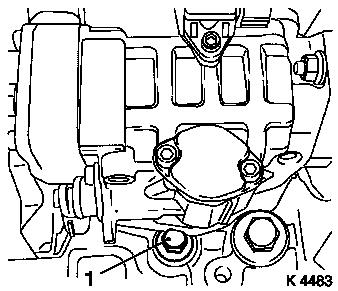
| 3. |
Drain engine oil
| • |
Place collecting basin underneath.
|
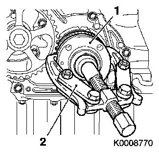
| • |
Unscrew oil filter housing cover (1)
|
| • |
Remove oil filter element
|
|
|
|
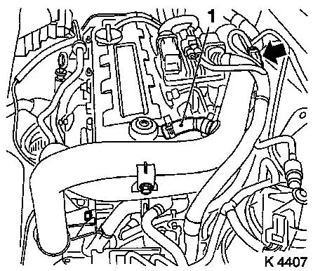
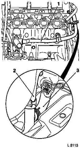
| 4. |
Remove air intake pipe
| • |
Detach engine vent hose (1)
| – |
From cylinder head cover
|
|
| • |
Unclip wiring harness (arrow)
|
|
|
|
| 5. |
Remove ribbed V-belt
| • |
Tension ribbed V-belt tensioner in direction of arrow
| – |
With KM-913-A
Note: Mark direction of
rotation
|
|
|
|
|
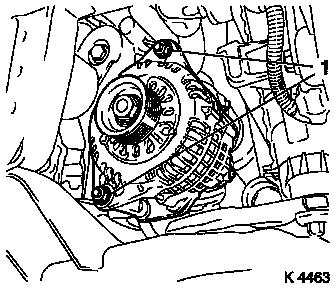
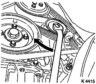
| 6. |
Remove starter alternator wiring harness
| • |
Disconnect alternator
| – |
Disconnect wiring harness plug (1)
|
|
| • |
Remove bracket with wiring harness
|
|
|
|
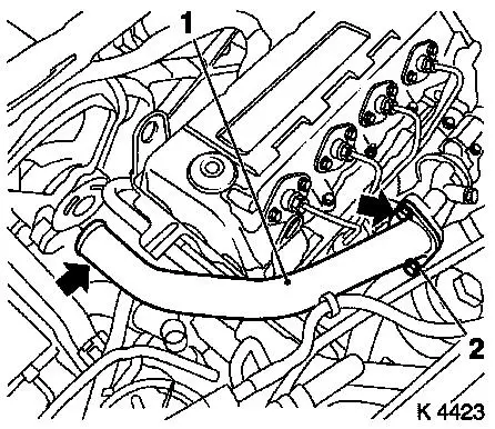
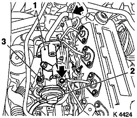
| 8. |
Remove oil dipstick guide tube bracket
|
| 9. |
Remove lower coolant hose
| • |
Place collecting basin underneath.
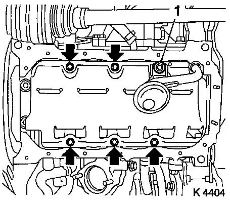
|
|
| 10. |
Remove oil dipstick guide tube
|
| 11. |
Remove exhaust manifold heat shield
|
|
|
| 12. |
Remove turbocharger heat shield
|
| 13. |
Detach vacuum hose from waste gate unit
|
| 14. |
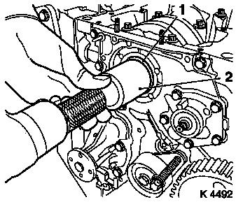
Remove turbocharger oil return hose (1)
|
|
|
| 15. |
Remove turbocharger oil feed line
| • |
Unscrew nut
Note: Counterhold at
threaded connection
|
|
|
|
| 16. |
Remove exhaust recirculation pipe
|
|
|
| 17. |
Loosen turbocharger bracket
|
| 18. |
Remove exhaust manifold
| • |
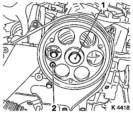
Unscrew 7 bolts, 2 nuts (1)
|
|
|
|
| 19. |
Remove alternator bracket
| • |
Remove 4 bolts (arrows)
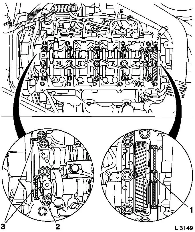
|
|
|
|
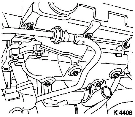
| 20. |
Remove coolant pipe (1)
| • |
Remove thermostat housing coolant hoses (2, 3)
|
| • |
Pull coolant tube out of coolant flange
|
|
|
|
| 21. |
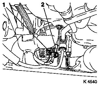
Remove coolant flange
|
| 22. |
Remove coolant drain screw
|
| 23. |
Remove oil circuit connecting pieces
|
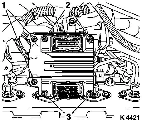
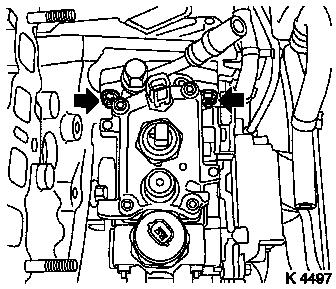
| 24. |
Remove engine control unit
| • |
Unscrew 2 bolts (2), 2 nuts (3)
|
| • |
Remove wiring harness plug bracket
|
|
|
|
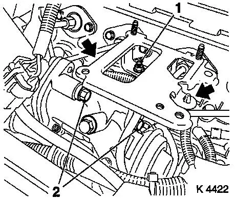
| 25. |
Remove engine control unit bracket
| • |
Unscrew 2 bolts (2), nut (1)
|
| • |
Unclip wiring harness (arrows)
|
|
|
|
| 26. |
Remove injection pump insulators
|
| 27. |
Remove engine management wiring harness
| • |
Disconnect wiring harness plug
| – |
Coolant temperature sensor, oil pressure switch, injection
pump, exhaust gas recirculation solenoid valve, sheathed glow
plugs, charge pressure sensor
|
|
|
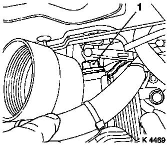
| 28. |
Remove upper charge air pipe (1)
| • |
Remove 2 bolts (arrows)
|
|
|
|
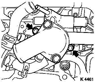
| 29. |
Remove exhaust recirculation valve (1)
| • |
Remove 2 bolts (arrows)
|
|
|
|
| 30. |
Remove oil filter housing
| • |
Detach coolant hoses
| – |
From oil filter housing
|
|
|
|
|
| 31. |
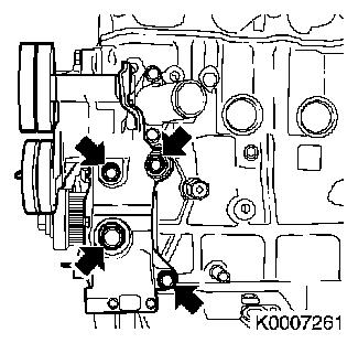
Remove thermostat housing
| • |
Remove 2 bolts (arrows)
|
|
|
|
| 32. |
Remove turbocharger vacuum hose
|
| 33. |
Remove oil pressure switch
|
| 35. |
Remove right rear engine transport shackle
|
| 36. |
Remove injection pump insulator
|
| 37. |
Remove injection pipe spacers (1)
Note: Mark spacer
positions
|
|
|
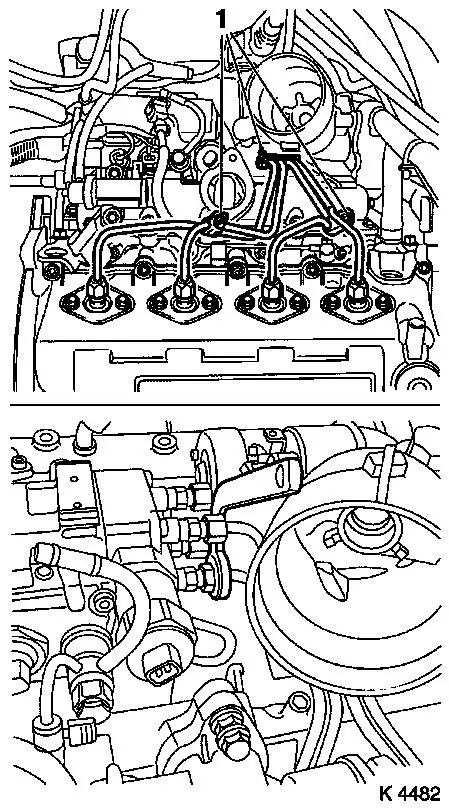
| 38. |
Remove injection lines
|
|
|
| 39. |
Remove oil leak line hose
|
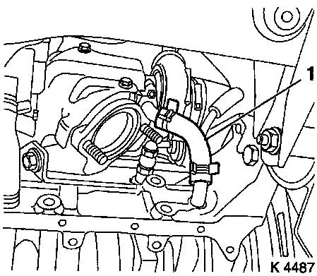
| 40. |
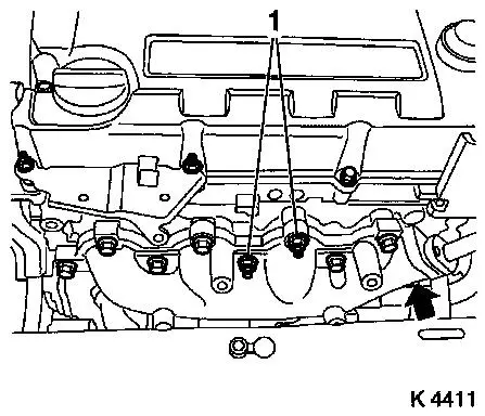
Remove intake manifold
| • |
Unscrew 7 bolts (1), 2 nuts (2)
|
|
|
|
| 41. |
Detach right engine bracket (1)
|
|
|
| 42. |
Remove coolant pump ribbed V-belt pulley
|
| 43. |
Remove coolant pump (1)
| • |
Place collecting basin underneath.
|
| • |
Remove coolant pump plastic insert
|
|
|
|
| 44. |
Remove upper toothed belt cover
| • |
Remove 8 bolts
Note: Note dissimilar
bolt lengths
|
| • |
Remove adapter for right engine bracket
|
|
|
|
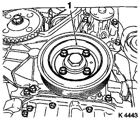
| 45. |
Remove torsional vibration damper (1)
|
|
|
| 46. |
Detach lower part of toothed belt cover
|
|
|
| 47. |
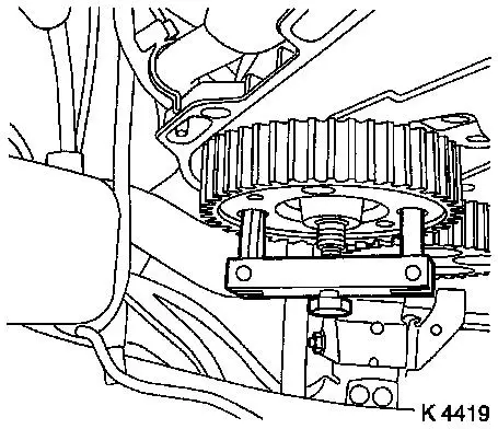
For toothed belt tension roller with leaf spring:
| • |
Remove toothed belt tensioner
| – |
Remove tension spring (1)
|
|
|
|
|
| 48. |
For toothed belt tension roller with spiral spring:
| • |
Remove toothed belt tension roller (1)
|
|
|
|
| 49. |
Detach camshaft pulley
| • |
Unscrew TDC-fixing bolt (2)
|
| • |
Counterhold camshaft pulley with KM-6156 and KM-956-1
|
|
|
|
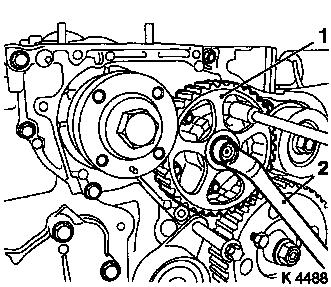
| 50. |
Remove drive gear injection pumps
| • |
Unscrew TDC-fixing bolt
|
Important: Note woodruff keys
|
| • |
Removing injection pump drive gear
|
|
|
|
| 51. |
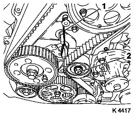
Remove toothed belt deflection pulley (1)
|
|
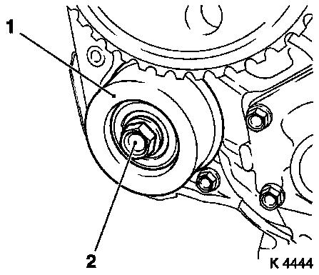
|
| 52. |
Remove toothed belt tension roller spring retainer
|
| 53. |
Remove rear toothed belt cover
|
| 54. |
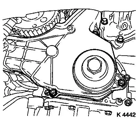
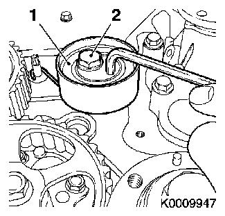
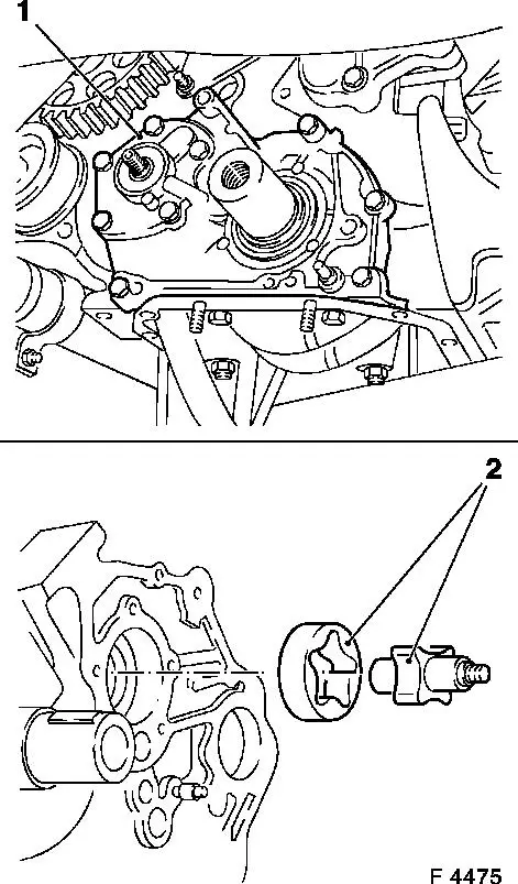
Remove oil pump drive gear (1)
| • |
Unscrew nut
Note: Counterhold with
socket wrench (2).
|
|
|
|
| 55. |
Remove crankshaft toothed belt drive gear (1)
|
|
|
| 56. |
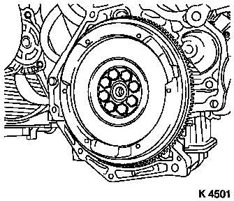
Remove clutch
Note: See operation
"Removing and installing pressure plate and clutch disk (without
SAC)" in group "K".
|
| 58. |
Remove injection pump holder (arrow)
|
|
|
| 59. |
Remove injection pump
| • |
Remove front injection pump insulation
|
|
|
|
| 60. |
Remove crankshaft sensor(1)
|
|
|
| 61. |
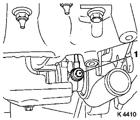
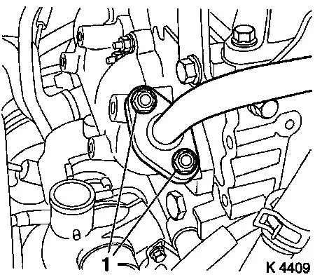
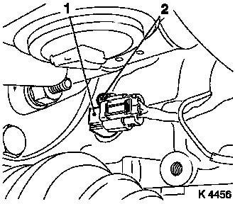
Remove oil pressure control valve (1)
|
|
|
| 63. |
Remove 2 engine transport shackles
|
| 64. |
Remove 4 outer injection nozzle seals
|
|
|
| 65. |
Remove camshaft housing cover
| • |
Unscrew 7 bolts (1), 3 studs (2)
|
|
|
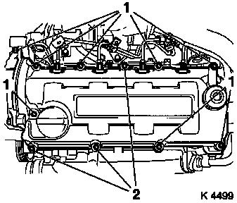
|
| 66. |
Remove inner oil leak line
| • |
Unscrew 5 banjo bolts (1)
Note: Note sealing
rings.
|
|
|
|
Important: Ensure that upon
removal of injector nozzles heat protection sleeves remain in their
position on the cylinder head. Otherwise, heat protection sleeves
must be removed completely and installed again using new sealing
rings. This is the only way to ensure that no coolant can reach the
combustion chamber, which would inevitably cause engine damage.
Replace heat protection sleeves – see operation "Replace heat
protection sleeves" in document "Check and measure cylinder
head".
|
| 67. |
Remove injector nozzles
|
| 68. |
Remove injector nozzles
| • |
Remove injection nozzle bracket
|
| • |
Remove injector nozzles
|
|
|
|
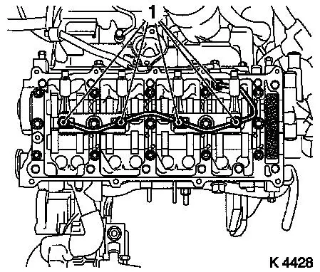
| 69. |
Remove camshaft housing cover
Important: Follow order.
|
| • |
Loosen bolts, stud bolts (180°)
|
| • |
Unscrew 2 stud bolts, 15 bolts
|
|
|
|
| 70. |
Remove cup tappets
| • |
Important! Note allocation and installation position
|
|
| 71. |
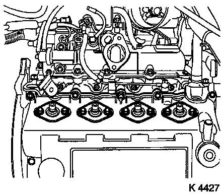
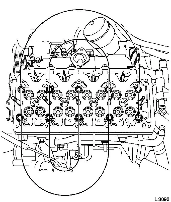
Remove cylinder head bolts
| • |
Remove 10 bolts
Note: Undo bolts in
depicted order (180° to 360°).
|
|
|
|
Important: Place cylinder head on
wooden blocks. Note sheathed glow plugs.
|
| 72. |
Remove cylinder head
Note: 2nd mechanic.
| • |
Remove cylinder head gasket
|
|
| 74. |
Screw in oil drain screw
| • |
Tighten oil drain screw ( 78.4
Nm )
|
|
| 75. |
Detach oil pan lower part
| • |
Remove using KM-J-37228
|
|
|
|
| 76. |
Detach oil pan upper part
| • |
Remove 14 bolts
Note: Note dissimilar
bolt lengths
|
| • |
Remove 2 nuts
Note: Use wide
spatula.
|
|
| 77. |
Detach oil intake pipe
|
| 78. |
Remove oil baffle plate
| • |
Remove 5 bolts (arrows)
|
|
|
|
| 79. |
Remove oil pump cover (1)
| • |
Remove 9 bolts
Note: Note dissimilar
bolt lengths
|
| • |
Remove inner and outer rotors (2)
|
|
|
|
| 80. |
Clean components
| • |
Oil pan lower section, oil pan upper section, cylinder head,
exhaust manifold, exhaust recirculation valve, coolant connections,
oil pump cover
|
|
| 82. |
Remove cylinder block
| • |
Attach transport shackles
|
| • |
Put down cylinder block
|
| • |
Remove transport shackles
|
|
| 83. |
Attach cylinder block
| • |
Attach transport shackles
|
| • |
Remove transport shackles
|
|
| 84. |
Drive in engine number
|
| 85. |
Drive guide bushings into cylinder block
|
| 86. |
Remove oil pump cover sealing rings
| • |
Front crankshaft sealing ring (1), oil pump sealing ring
(2)
Important: Do not damage sealing
surfaces.
|
| – |
Prise out sealing rings
|
|
|
|
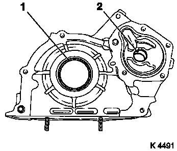
|
| 87. |
Attach oil pump cover (2)
| • |
Insert inner and outer rotor
|
| • |
Apply adhesive sealing compound (black) (shaded area)
|
| • |
Attach oil pump cover
Note: Note guide
bushings and differing bolt lengths.
| – |
Tighten bolts ( 9.8 Nm )
|
|
|
|
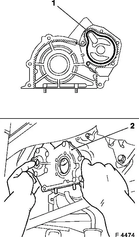
|
| 88. |
Install oil pump seal ring
| • |
Coat sealing lip with silicon grease (white)
|
| • |
Drive in until flush using KM-657
|
|
| 89. |
Install front crankshaft sealing ring (1)
| • |
Coat sealing lip with silicon grease (white)
|
| • |
Drive in until flush using KM-656
(2)
|
|
|
|
| 90. |
Install oil baffle plate
| • |
Tighten bolts ( 18.6 Nm )
|
|
| 91. |
Attach oil intake pipe
| • |
Tighten bolt ( 18.6 Nm )
|
|
| 93. |
Attach oil pan upper part
Important: The application of
silicone sealing compound (grey) and installation of lower part of
oil pan including torque test must be performed within 10
minutes!
|
| • |
Apply silicon sealing compound (grey)
|
| • |
Tighten bolts, nuts ( 9.8 Nm
)
|
|
| 94. |
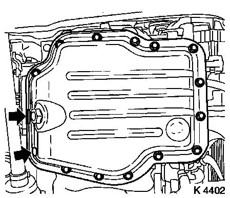
Attach oil pan lower section
| • |
Apply silicon sealing compound (grey)
|
| • |
Tighten bolts ( 9.8 Nm )
|
|
| 96. |
Attach flywheel
| • |
Tighten bolts ( 29,4 Nm + 60° +
15° )
|
|
| 97. |
Install clutch
Note: See operation
"Removing and installing pressure plate and clutch disk (without
SAC)" in group "K".
|
| 99. |
Attach crankshaft toothed belt drive gear
| • |
Install sheet metal panel
|
| • |
Insert toothed belt drive gear in place
|
| • |
Counterhold using KM-662-C
|
| • |
Tighten bolt ( 196 Nm )
|
|
| 100. |
Check for plane surface
| • |
Cylinder head, cylinder block
|
| • |
With straightedge, feeler gauge
|
|
|
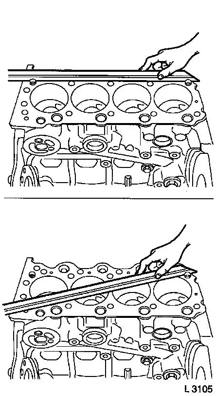
|
| 101. |
Measure piston projection
| • |
Insert MKM-571-B (1) into KM-301 (2)
|
| • |
Set dial to zero
| – |
Place probe on cylinder block
|
|
| • |
Measure piston projection on all four pistons
| – |
Carry out measurement on two different locations (3 and 4) or
(5 and 6)
|
| – |
Determine high point by turning crankshaft
|
|
| • |
Turn crankshaft
| – |
approx. 60° before TDC of cylinder-1
|
|
|
|
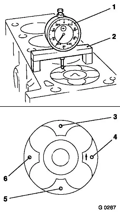
|
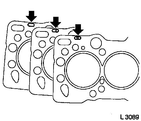
| 102. |
Replace cylinder head gasket
|
Piston projection
|
Thickness of cylinder head gasket
|
Code
|
|
0.630 – 0.696 mm
|
1.45 mm
|
no hole
|
|
0.697 – 0.763 mm
|
1.50 mm
|
one hole
|
|
0.764 – 0.830 mm
|
1.55 mm
|
two holes
|
Important: The largest determined
piston projection determines the selection of the cylinder head
gasket with appropriate identification (arrows).
|
| • |
Lay cylinder head gasket in place
|
|
|
|
| 103. |
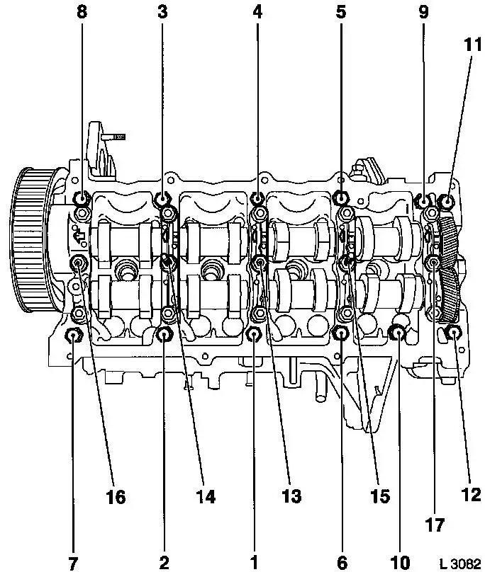
Attach cylinder head
Note: 2nd mechanic.
|
| 104. |
Fasten cylinder head
| • |
Replace cylinder head bolts
| – |
Screw in bolts by several threads
|
|
Important: Note tightening
order.
|
| • |
Tighten cylinder head bolts ( 39.2 Nm +
60° + 13°+ 60° + 13° )
|
|
|
|
| 105. |
Insert cup tappets
Important: Note order and
allocation.
|
| • |
Coat with engine oil
|
|
| 106. |
Install camshaft housing
| • |
Tighten bolts M8 ( 21.6 Nm )
|
Important: Follow order.
|
| • |
Tighten bolts M10 ( 43.1 Nm
)
|
|
|
|
| 107. |
Install safety valve
| • |
Tighten bolt ( 39.2 Nm )
|
|
| 108. |
Install oil pressure control valve
| • |
Tighten oil pressure regulating valve ( 29.4 Nm )
|
|
| 109. |
Install crankshaft sensor
| • |
Tighten bolt ( 9.8 Nm )
|
|
| 110. |
Install injection pump
| • |
Insert front injection pump insulation
Note: Note central
position of stud in injection pump flange.
|
|
| 111. |
Attach rear toothed belt cover
| • |
Tighten bolts ( 9.8 Nm )
|
|
| 112. |
Attach toothed belt clamping roller spring retainer
| • |
Tighten bolts ( 9.8 Nm )
|
|
| 113. |
Install oil pump drive gear
Note: Pay attention to
installation position
| • |
Tighten nut ( 44.1 Nm )
|
|
| 114. |
Install toothed belt guide roller
| • |
Tighten bolt ( 80.4 Nm )
|
|
| 115. |
Install injection pump drive gear
Important: Observe tightening
sequence
| 1. |
Tighten nut 60 Nm
|
| 2. |
Loosen nut |
| 3. |
Waiting time: 60 sec |
| 4. |
Tighten nut 60 Nm
|
|
| • |
|
|
| 116. |
Attach camshaft pulley
| • |
Block using KM-6156 and KM-956-1
|
| • |
Tighten bolt ( 63.7 Nm )
|
| • |
Install TDC-fixing bolt
|
|
| 117. |
Install toothed belt tension roller
| • |
Screw in toothed belt tension roller bolt
|
| • |
For toothed belt tension roller with leaf spring: unscrew bolt
(M10) from lower bore of toothed belt tensioner
|
|
| 118. |
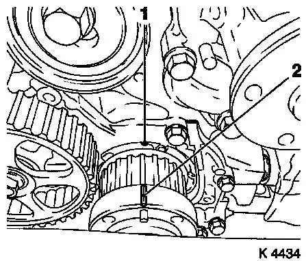
Set no.1 cylinder to TDC
| • |
Mark on toothed belt drive gear (2) must align with casting lug
at oil pump cover (1)
|
|
|
|
| 119. |
Install toothed belt
| • |
Position toothed belt
Note: Toothed belt must
be taut from toothed belt drive gear via oil pump drive gear and
injection pump drive gear
|
| • |
For toothed belt tension roller with leaf spring:
|
| • |
Unscrew TDC-fixing bolt
|
| • |
Rotate crankshaft 60° against direction of engine
rotation
|
| • |
Tighten bolt of toothed belt tension roller
| – |
For toothed belt tension roller with spiral spring 49 Nm
|
| – |
For toothed belt tension roller with leaf spring 38.2 Nm
|
|
| • |
For toothed belt tension roller with leaf spring: unscrew bolt
(M10) from lower bore of toothed belt tensioner
|
|
| 120. |
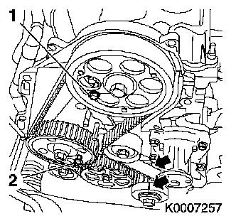
Timing, Check
| • |
Turn crankshaft approx. 780° in direction of engine
rotation
| – |
At toothed belt drive gear bolt
|
|
| • |
The mark on toothed belt drive gear must align with lug on oil
pump cover (arrows)
|
| • |
Install TDC-fixing bolt
| – |
Injection pump drive gear M8 (2)
Note: If the TDC fixing
bolts cannot be screwed in, basic adjustment must be repeated
|
|
| • |
Unscrew TDC-fixing bolts
|
|
|
|
| 122. |
Attach KM-798
| • |
Turn crankshaft in direction of engine rotation to 45°
before no.1 cylinder TDC
| – |
At toothed belt drive gear bolt
|
|
| • |
Remove central bleeder screw
|
| • |
Install KM-798 under pre-tension
|
| • |
Determine BDC position of injection pump plunger by turning
crankshaft back and forth
Note: Dial gauge needle
must not move
|
|
|
|
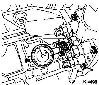
| 123. |
Adjust injection pump
| • |
Turn crankshaft to no.1 cylinder TDC
Note: Mark on toothed
belt drive gear must align with casting lug at oil pump cover.
|
| • |
Loosen diesel injection pump
|
| • |
Turn diesel injection pump until 0.33 mm adjustment value is
accomplished
| – |
Value too high – turn injection pump towards engine
|
| – |
Value too low – turn injection pump away from engine
|
|
| • |
Tighten diesel injection pump ( 19.6
Nm )
|
|
| 124. |
Check start of feed
| • |
Turn crankshaft approx. 675°
|
| • |
Install KM-798 under pre-tension
|
| • |
Determine BDC position of injection pump plunger by turning
crankshaft back and forth
Note: Dial gauge needle
must not move
|
| • |
Turn crankshaft to 1st Cylinder TDC
Note: Mark on toothed
belt drive gear must align with casting lug at oil pump cover.
|
Important: Repeat adjustment if
test value is not achieved!
|
| • |
Read test value
| – |
Test value: 0.28 – 0.38 mm
|
|
|
| 125. |
Remove KM-798
| • |
Tighten central bleeder screw ( 23.5
Nm )
|
|
| 126. |
Attach injection pump bracket
| • |
Tighten bolts to cylinder block ( 53.9
Nm )
|
| • |
Tighten bolt to injection pump ( 18.6
Nm )
|
|
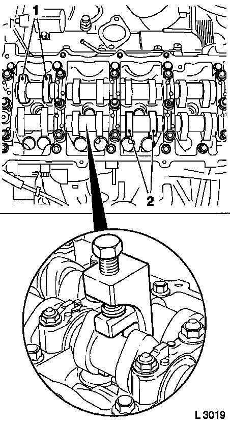
| 127. |
Turn crankshaft
| • |
Turn crankshaft until cam pairs (1) and (2) point upwards
|
|
|
|
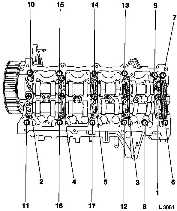
| 128. |
Check valve clearance
| • |
Using feeler gauge
| – |
Test values: Intake valves/Exhaust valves (0.35 – 0.45
mm)
|
|
|
| 129. |
Adjust valve clearance
| • |
Turn cup tappet until tappet groove points outwards
|
Important: Ensure that valves do
not interfere with piston head
|
| • |
Press down cup tappets using KM-6090
Note: Note different
tool versions for intake and exhaust valves
| – |
Mark – IN = Intake side
|
| – |
Mark – EX = Exhaust side
|
|
| • |
Remove adjustment shim
Example for determination of shim thickness
|
1.
|
Thickness of installed shim
|
|
3.15 mm
|
|
2.
|
Measurement between cam and cup tappets
|
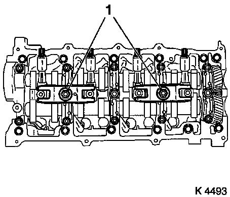
+
|
0.45 mm
|
|
|
|
=
|
3.60 mm
|
|
3.
|
Nominal valve play
|
-
|
0.40 mm
|
|
4.
|
Thickness of new shim
|
=
|
3.20 mm
|
|
|
| 130. |
Insert adjustment shim
| • |
Coat new shim (7) with engine oil and insert in cup tappet with
identification mark facing downwards
|
|
|
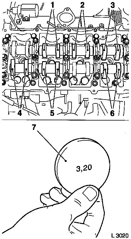
|
| 131. |
Check and adjust valve clearance
| • |
In direction of engine rotation by 180°
| – |
Check and adjust valve pair (6) and (2)
|
|
| • |
In direction of engine rotation by 180°
| – |
Check and adjust valve pair (5) and (3)
|
|
| • |
In direction of engine rotation by 180°
Note: Clearance of all
adjusted valves must be re-checked
| – |
Check and adjust valve pair (4) and (1)
|
|
|
|
|
| 132. |
Install injector nozzles
| • |
Replace copper seal rings (2)
|
| • |
Insert injection nozzles in cylinder head.
|
| • |
Install injection nozzle bracket
|
| • |
Attach injection nozzle bracket ( 22.1
Nm )
|
|
|
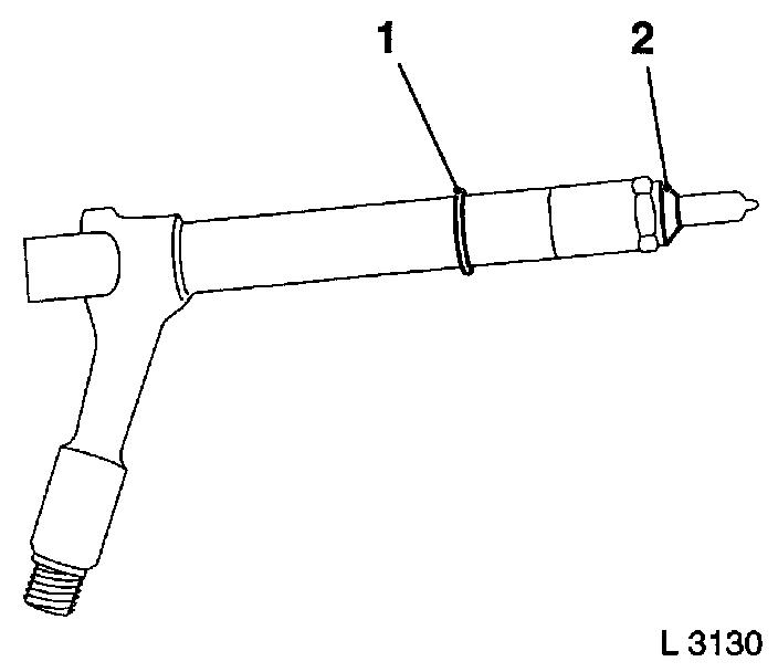
|
| 133. |
Install inner oil leak line
| • |
Tighten banjo bolt ( 14.7 Nm
)
|
|
| 134. |
Install camshaft housing cover
Important: Oil return bore (2)
must not be covered with adhesive sealing compound or by the
camshaft housing cover gasket
|
| • |
Apply adhesive sealant compound (white)
|
| • |
Tighten bolts, studs ( 9.8 Nm
)
|
|
|
|
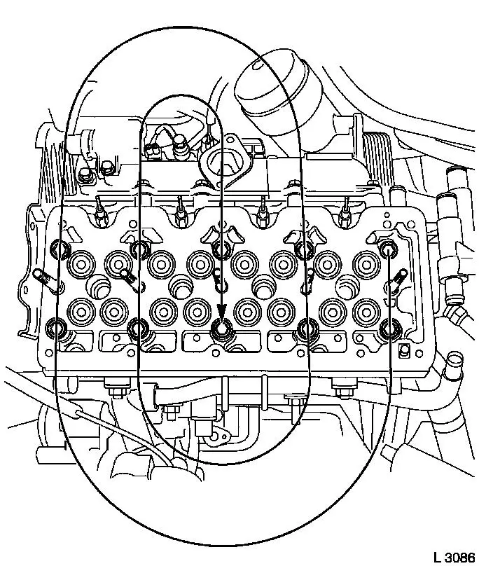
| 135. |
Install outer injection nozzle seal
| • |
Replace seals
Note: Pay attention to
installation position
|
|
| 136. |
Attach engine transport shackles
| • |
Tighten bolts ( 24.5 Nm )
|
|
| 137. |
Install lower toothed belt cover
| • |
Tighten bolts ( 9.8 Nm )
|
|
| 138. |
Install torsional vibration damper
| • |
Tighten bolts ( 19.6 Nm )
|
|
| 139. |
Install right engine bracket adapter
| • |
Insert lower bolt
| – |
Into right engine bracket and right engine bracket adapter
|
|
| • |
Insert right engine bracket, right engine bracket adapter,
upper part of toothed belt cover
|
| • |
Tighten 3 bolts( 40 Nm )
|
|
| 140. |
Install upper toothed belt cover
| • |
Tighten bolts ( 9.8 Nm )
Note: Note dissimilar
bolt lengths
|
|
| 141. |
Install coolant pump
| • |
Tighten bolts ( 23.5 Nm )
|
|
| 142. |
Install coolant pump ribbed V-belt pulley
| • |
Tighten bolts ( 9.8 Nm )
|
|
| 143. |
Install intake manifold
| • |
Tighten bolts, nuts ( 24.5 Nm
)
|
|
| 144. |
Install oil leak line hose
|
| 145. |
Install injection lines
| • |
Important! Injection lines must be installed without tension.
Hand-tighten at injector nozzles and injection pump.
|
| • |
Tighten union nut ( 22.5 Nm
)
|
|
| 146. |
Install injection line spacers
Note: Pay attention to
spacer positions
|
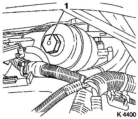
| 147. |
Install starter
| • |
Tighten lower bolt ( 38.2 Nm
)
|
|
| 148. |
Attach oil filter housing
| • |
Tighten bolt ( 23.5.5 Nm )
|
|
| 149. |
Install oil filter element
| • |
Tighten oil filter housing cover ( 23.5
Nm )
|
|
| 150. |
Install right rear engine transport shackle
| • |
Tighten bolt ( 24.5 Nm )
|
|
| 151. |
Install exhaust gap return valve
| • |
Tighten studs, bolts
| – |
At intake manifold ( 24.5 Nm
)
|
|
|
| 152. |
Attach upper charge air pipe
| • |
Upper charge air pipe bracket to camshaft housing
| – |
Tighten bolt ( 24.5 Nm )
|
|
|
| 153. |
Install oil pressure switch
Note: Clean thread in
cylinder head.
| • |
Apply silicon sealing compound (grey) to thread
|
| • |
Tighten oil pressure switch ( 20.6
Nm )
|
|
| 154. |
Install turbocharger vacuum hose
|
| 155. |
Attach thermostat housing
| • |
Tighten bolts ( 23.5 Nm )
|
|
| 156. |
Install motor management wiring harness
| • |
Connect wiring harness plug.
| – |
Coolant temperature sensor, oil pressure switch, injection
pump, exhaust gas recirculation solenoid valve, sheathed glow
plugs, charge pressure sensor
|
|
|
| 157. |
Install injection pump insulation
|
| 158. |
Install engine control unit bracket
| • |
Tighten bolts, nut ( 9.8 Nm
)
|
| • |
Attach engine management wiring harness bracket
|
| • |
Clip in engine management wiring harness
|
|
| 159. |
Install engine control unit
| • |
Tighten bolts, nuts ( 5.9 Nm
)
|
| • |
Attach engine management wiring harness plug
Note: Note installation
direction.
|
| • |
Install wiring harness plug bracket
|
|
| 160. |
Attach coolant drain screw
|
| 161. |
Attach oil circuit connection pieces
|
| 162. |
Attach coolant flange
| • |
Apply adhesive sealant compound (light grey)
|
|
| 163. |
Attach coolant pipe
| • |
Tighten bolt ( 95.1 Nm )
|
|
| 164. |
Attach alternator bracket
| • |
Tighten bolts M10 ( 48 Nm )
|
| • |
Tighten bolts M14 ( 67.6 Nm
)
|
|
| 165. |
Attach exhaust manifold
| • |
Tighten bolts, nuts ( 23.5 Nm
)
|
|
| 166. |
Attach turbocharger bracket
|
| 167. |
Attach exhaust gas recirculation pipe
| • |
Tighten bolts( 28.4 Nm )
|
|
| 168. |
Attach turbocharger oil feed line
| • |
Tighten banjo bolt ( 9.8 Nm
)
|
| • |
Tighten nuts ( 9.8 Nm)
Note: Counterhold at
threaded connection
|
|
| 169. |
Install turbocharger oil return hose
|
| 170. |
Attach waste gate unit vacuum hose
|
| 171. |
Install turbocharger heat shield
| • |
Tighten bolts ( 11.7 Nm )
|
|
| 172. |
Install exhaust manifold heat shield
| • |
Tighten bolts ( 11.7 Nm )
|
|
| 173. |
Install oil dipstick guide tube
| • |
Tighten bolts ( 9.8 Nm )
|
|
| 174. |
Attach lower coolant hose
|
| 175. |
Install oil dipstick guide tube bracket
| • |
Tighten nuts ( 9.8 Nm )
|
|
| 176. |
Attach alternator
| • |
Install oil feed line
| – |
Tighten banjo bolt ( 21.6 Nm
)
|
|
|
| 177. |
Install starter alternator wiring harness
| • |
Starter
| – |
Tighten nuts ( 9.8 Nm )
|
|
| • |
Attach bracket with wiring harness
|
| • |
Route wiring harness and clip in
|
| • |
Connect alternator
| – |
Connect wiring harness plug.
|
|
|
| 178. |
Install ribbed V-belt
Note: Observe running
direction
| • |
Release ribbed V-belt tensioner
|
|
| 179. |
Install air intake pipe
| • |
Attach engine vent hose
|
|
| 180. |
Pour in engine oil
| • |
Observe specified engine oil quantity
|
|
| 181. |
Attach manual transmission to engine
Note: See operation "J
450100 007 Detaching and attaching manual transmission from/to
engine".
|
| 182. |
Install engine
Note: See operation "J
450100 Removing and installing engine".
|
|