|
J 312315 replace valve stem seal (Z 14 XE, Z 16
YNG with air conditioning, RHD)
|
1. Open bonnet
Important: On
vehicles as of model year 04 with ESP - the steering angle sensor
loses its basic adjustment each time the battery is disconnected.
It must be recalibrated.
2. Disconnect battery
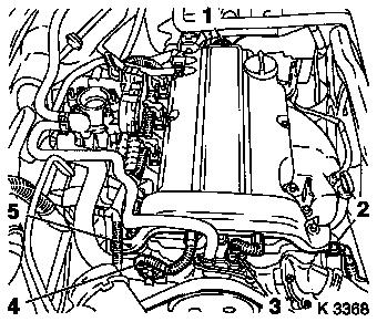
3. Remove engine cover.
- Unscrew oil filler pipe cap
- Remove 2 bolts
- Screw on oil filler pipe cap
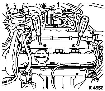
4. Remove air cleaner housing (1)
- Disconnect wiring harness plug
- Intake air temperature sensor (4), tank vent valve (2)
- Unclip tank vent valve
- Remove air intake hose
- Detach engine vent hose (5)
- Unscrew bolts (3)
|
|
|
5. Loosen front right wheel
6. Raise vehicle
7. Remove front right wheel
8. Raise vehicle
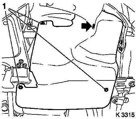
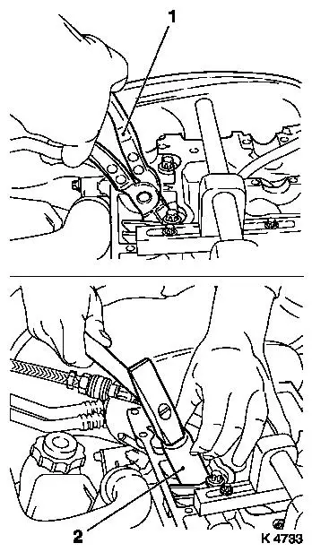
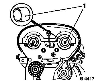
9. Remove ribbed V-belt cover
- Remove 3 bolts (1)
- Remove clip (arrow).
|
|
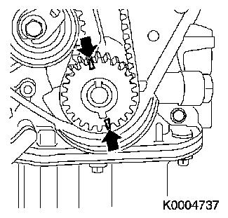
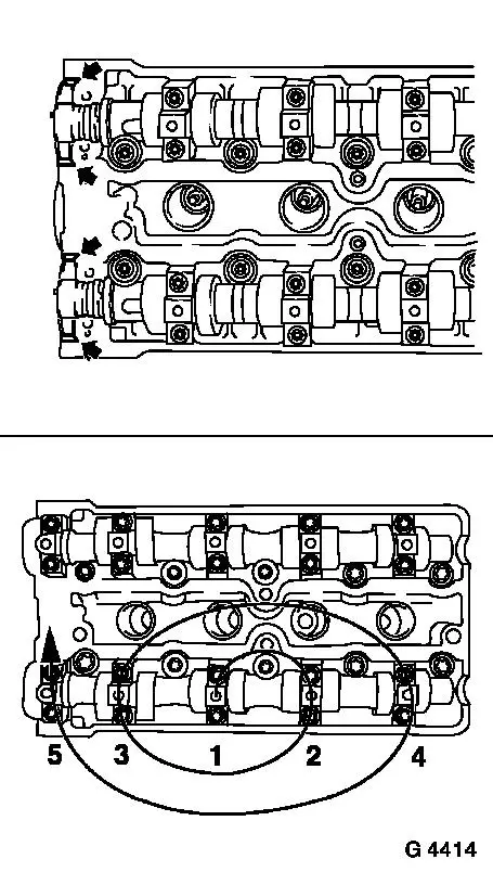
|
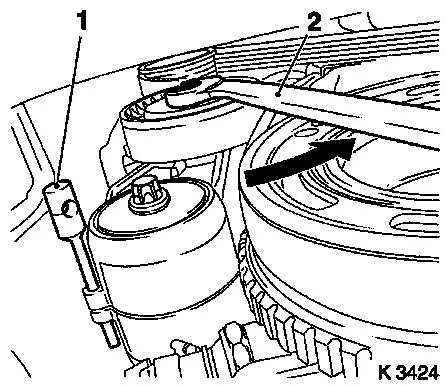
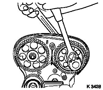
10. Remove ribbed V-belt
- Tension ribbed V-belt tensioner in direction of arrow
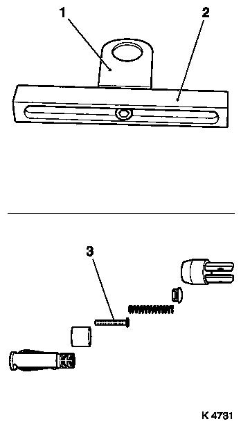
- With KM-913-A (2) (SW 15)
- Insert KM-6130 (1)
- Note: Mark running direction
|
|
|
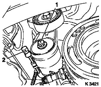
11. Remove ribbed V-belt tensioner
- Tension ribbed V-belt tensioner.
- Remove KM-6130 (2)
- Release ribbed V-belt tensioner
- Remove bolt (1)
|
|
|
12. Detach crankshaft ribbed V-belt pulley
- Lever out front closure plug
- Insert KM-911
- Remove bolt
- Remove KM-911
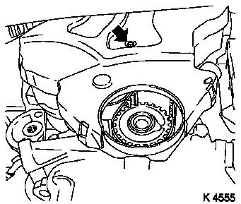
13. Loosen lower part of toothed belt cover
- Remove bolt (arrow)
- Unclip from rear toothed belt cover
|
|
|
14. Lower vehicle
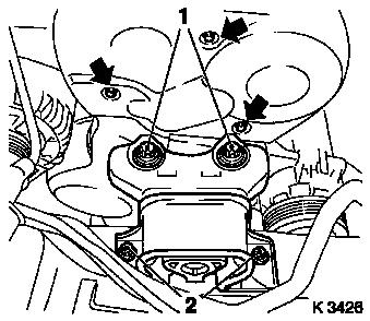
15. Remove toothed belt cover upper
part
- Remove 3 bolts (arrows)
- Unclip from rear toothed belt cover
|
|
|
16. Remove lower part of toothed belt cover
- Unclip from rear toothed belt cover
- Note: Remove downwards
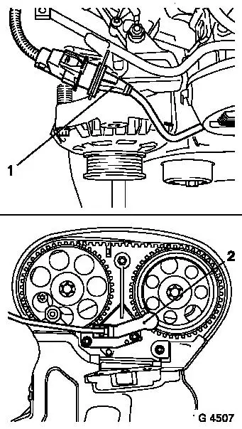
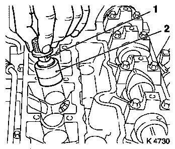
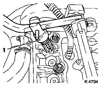
17. Disconnect camshaft sensor wiring harness plug
- Unclip out of bracket
- Disconnect wiring harness plug (1)
18. Remove camshaft sensor (2)
|
|
|
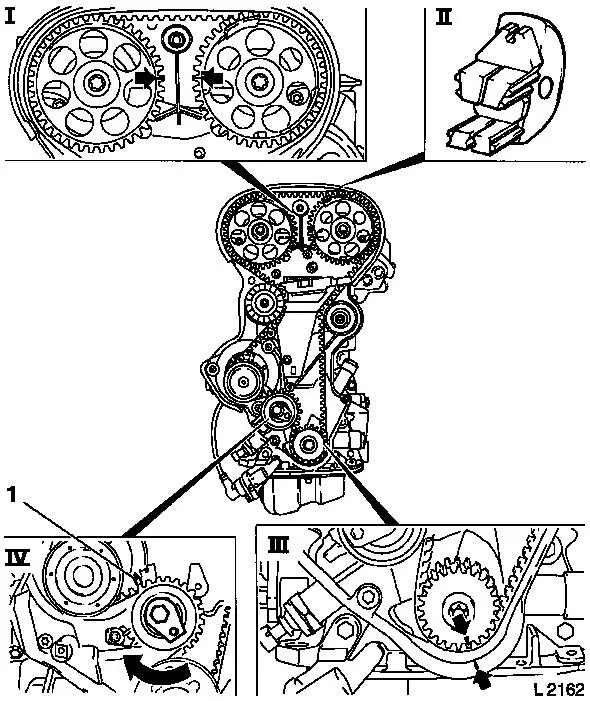
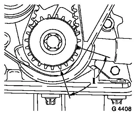
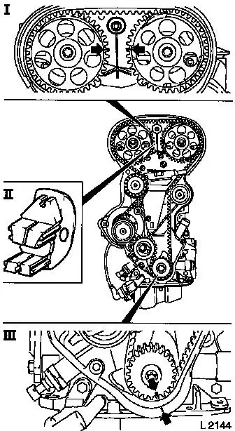
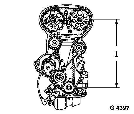
19. Set 1st cylinder to TDC
- Install crankshaft V-belt pulley bolt
- Set crankshaft to mark.
- Turn crankshaft evenly
- Note: Marks on drive gear toothed belt and rear toothed belt
cover must align (III)
- Fix camshaft sprockets in position.
- Note: Marks must be opposite one another and aligned with the
top edge of the cylinder head (I)
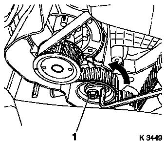
- Insert KM-852 (II)
20. Remove toothed belt
- Release toothed belt tension roller (IV)
- Loosen bolt
- Turn adjusting eccentric in direction of arrow (clockwise)
until pointer (1) of the toothed belt tension roller is located
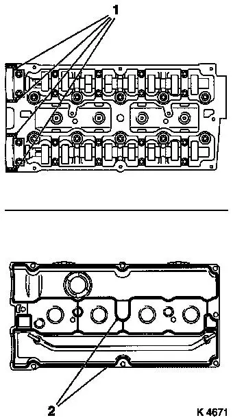
just before left stop.
|
|
|
21. Remove ignition module
- Disconnect wiring harness plug
- Remove 4 bolts
- Remove using KM-6009 (1)
- Caution: Do not tilt
|
|
|
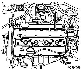
22. Remove cylinder head cover
- Detach engine vent hose
- Detach crankshaft vent hose
- Remove 10 bolts
- Remove seal
- Detach wiring harness plug for temperature sensor
|
|
|
23. Remove KM-852
24. Remove exhaust camshaft sprocket
- Remove bolt
- Counterhold camshaft at hexagonal section
25. Remove intake camshaft sprocket
- Remove bolt
- Counterhold camshaft at hexagonal section
|
|
|
26. Loosen upper rear toothed belt cover
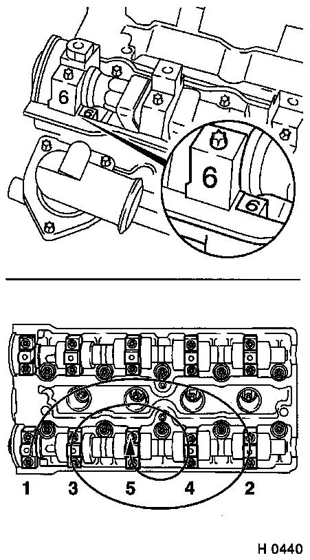
27. Remove exhaust camshaft
- Remove camshaft bearing cap
- Unscrew 10 bolts
- Caution: Note identification
- Release camshaft bearing cap working in inward spiral from
outside in steps of 1/2 to 1 turn
- Note: Camshaft must be evenly released from the bearing
seats
- Remove camshaft seal ring
|
|
|
28. Remove hydraulic valve lifter (2)
29. Remove intake camshaft
- Remove camshaft bearing cap
- Unscrew 10 bolts
- Caution: Note identification
- Release camshaft bearing cap working in inward spiral from
outside in steps of 1/2 to 1 turn
- Note: Camshaft must be evenly released from the bearing
seats
- Remove camshaft seal ring
|
|
|
30. Remove hydraulic valve lifter
31. Remove spark plugs
- 4 off
- Remove using KM-194-E
32. Raise vehicle
33. Attach guide mark
- On drive gear toothed belt
- Note: Offset 180° from 1st cylinder TDC mark
(Zünd-OT-Zylinder-1) (arrows)
|
|
34. Lock crankshaft
35. Lower vehicle
|
36. Assemble automatic valve spring
compressor
- Adjust supports
- Note: Adjust support heads (1) in the centre to support feet
(2) and tighten
- Assemble lever arm
- Assemble assembly kit
- Insert thrust piece 6a (3)
- Note: Observe manufacturer's instructions
|
|
|
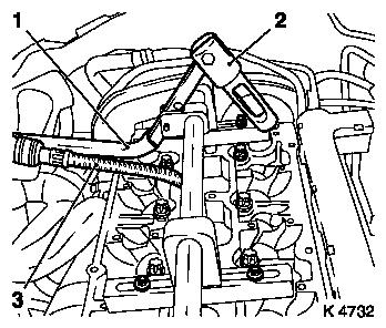
37. Attach automatic valve spring compressor
- Attach supports
- At position of camshaft bearing caps 1 and 4
- Slide installation shaft into supports
- Note: Align installation shaft in the centre above spark plug
bore
- Tighten 4 bolts
- Install lever arm (1)
- Note: Removal head (2) must face intake side
- Secure installation shaft
38. Install compressed air adapter (3)
- Screw into spark plug thread of 1st cylinder
- Apply compressed air to 1st cylinder
|
|
|
39. Remove intake valve springs for 1st cylinder
- 2 off
- Carefully push valve springs downwards
- With lever arm
- Note: Removal head must be positioned vertically above the
valve stem
- Remove valve keepers, valve head, valve spring
- Note: Do not use magnetic tool
40. Replace valve stem seals
- 2 off
- Detach using KM-840 (1)
- Attach new valve stem seal to valve stem
- Drive in to stop using KM-835-A (2)
|
|
|
41. Install intake valve springs for
1st cylinder
- Insert valve spring, valve head
- Insert valve keepers (1) in assembly head
- Slide clamping sleeve (2) in direction of lever arm mount
- Caution: Insert valve keepers with taper towards valve
- Push clamping sleeve towards valve
- Attach assembly head to lever arm
- Carefully push valve springs downwards
- With lever arm
- Caution: Installation head must be positioned vertically above
the valve stem.
- Note: Valve keepers must engage audibly.
|

|
42. Check installation position
- Caution: Do not attempt a second time without checking that
both valve keepers are seated in the assembly head. Check seating
of valve keepers. Verify pressurisation
43. Transfer lever arm
- Remove lever arm
- Detach assembly head
- Attach removal head
- Install lever arm
- Note: Removal head must face exhaust side
|
44. Remove exhaust valve springs for
1st cylinder
- 2 off
- Carefully push valve springs downwards
- With lever arm
- Note: Removal head (1) must be positioned vertically above the
valve stem
- Remove valve keepers, valve head, valve spring
- Note: Do not use magnetic tool
|
|
45. Replace valve stem seals
- 2 off
- Detach using KM-840
- Attach new valve stem seal to valve stem
- Drive in to stop using KM-835-A
46. Install exhaust valve springs for 1st cylinder
- Insert valve springs, valve head
- Insert valve keepers in assembly head
- Push clamping sleeve towards lever arm mount
- Caution: Insert valve keepers with taper towards valve
- Push clamping sleeve towards valve
- Attach assembly head to lever arm
- Carefully push valve springs downwards
- With lever arm
- Caution: Installation head must be positioned vertically above
the valve stem.
- Note: Valve keepers must engage audibly
47. Check installation position
- Caution: Do not attempt a second time without checking that
both valve keepers are seated in the assembly head. Check seating
of valve keepers. Verify pressurisation
48. Transfer compressed air adapter
- Interrupt compressed air feed
- Unscrew from spark plug thread of 1st cylinder
- Screw into spark plug thread of 4th cylinder
- Apply compressed air to 4th cylinder
|
49. Transfer lever arm
- Loosen installation shaft
- Remove lever arm
- Detach assembly head
- Attach removal head
- Install lever arm
- Secure installation shaft
|
|
50. Replace valve stem seals for 4th cylinder
51. Interrupt compressed air feed
52. Raise vehicle
53. Remove KM-911
54. Set 3rd cylinder to TDC
- Turn crankshaft evenly (180°)
- Note: Guide mark on drive gear toothed belt must be aligned
with mark on rear toothed belt cover
55. Lock crankshaft
56. Lower vehicle
57. Transfer automatic valve spring compressor
- Transfer supports
- At position of camshaft bearing caps 1 and 5
- Slide installation shaft into supports
- Note: Align installation shaft in the centre above spark plug
bore
- Tighten 4 bolts
- Install lever arm
- Note: Removal head must face intake side
- Secure installation shaft
|
58. Transfer compressed air adapter
- Out of spark plug thread of 4th cylinder
- Screw into spark plug thread of 2nd cylinder
- Apply compressed air to 2nd cylinder
|
|
59. Replace valve stem seals for 2nd cylinder
60. Transfer compressed air adapter
- Interrupt compressed air feed
- Unscrew from spark plug thread of 2nd cylinder
- Screw into spark plug thread of 3rd cylinder
- Apply compressed air to 3rd cylinder
61. Replace valve stem seals for 3rd cylinder
62. Interrupt compressed air feed
63. Detach automatic valve spring compressor
64. Remove compressed air adapter
65. Inspect components
- Camshafts, camshaft bearing caps, hydraulic valve lifters,
cylinder head, ribbed V-belt, ribbed V-belt tensioner, ribbed
V-belt pulleys, toothed belt drive, spark plugs
66. Install spark plugs
- Tighten using KM-194-E (25 Nm / 18.5 lbf. ft.)
67. Raise vehicle
68. Remove KM-911
|
69. Position crankshaft
- Note: Adjust crankshaft 60° in front of ign. TDC for
cylinder 1
|
|
|
70. Lower vehicle
71. Clean cylinder head
72. Install hydraulic valve lifters
- 8 off
- Coat sliding surfaces with engine oil
- Caution: Note allocation
73. Install intake camshaft
- Coat sliding surfaces with engine oil
- Apply sealant
- In camshaft seal ring area (arrows)
- Caution: Do not apply sealant to oil duct area. Complete
assembly operations within 10 minutes
- Insert camshaft, camshaft bearing cap
- Caution: Note mark and allocation
- Install camshaft bearing cap
- Tighten camshaft bearing caps in spiral pattern from inside
outwards (8 Nm / 6 lbf. ft.)
- Remove excess sealant
|
|
74. Install hydraulic valve lifters
- 8 off
- Coat sliding surfaces with engine oil
- Caution: Note allocation
75. Install exhaust camshaft
- Coat sliding surfaces with engine oil
- Apply sealant
- In camshaft seal ring area
- Caution: Do not apply sealant to oil duct area. Complete
assembly operations within 10 minutes
- Insert camshaft, camshaft bearing cap
- Caution: Note mark and allocation
- Install camshaft bearing cap
- Tighten camshaft bearing caps in spiral pattern from inside
outwards (8 Nm / 6 lbf. ft.)
- Remove excess sealant
|
76. Install intake camshaft seal ring
- Replace seal ring
- Coat seal lip with grease
- Place seal ring on camshaft journal
- Install camshaft seal ring
- With KM-422 (1), bolt and washer of crankshaft pulley
77. Install exhaust camshaft seal ring
- Replace seal ring
- Coat seal lip with grease
- Place seal ring on camshaft journal
- Install camshaft seal ring
- With KM-422, bolt and washer of crankshaft pulley
|
|
78. Fasten upper rear toothed belt cover
- Tighten bolts (6 Nm / 4.4 lbf. ft.)
79. Install intake camshaft sprocket
- Replace bolt
- Note: 2 people
- Tighten bolt (50 Nm / 37 lbf. ft. + 60° + 15°)
- Counterhold camshaft at hexagonal section
80. Install exhaust camshaft sprocket
- Replace bolt
- Note: 2 people
- Tighten bolt (50 Nm / 37 lbf. ft. + 60° + 15°)
- Counterhold camshaft at hexagonal section
|
81. Lock camshaft pulleys
- Note: Marks must be opposite one another and aligned with the
top edge of the cylinder head (I)
- Insert KM-852 (II)
- Turn the camshafts at hexagonal section
82. Lock crankshaft
- Set crankshaft to mark.
- Turn crankshaft evenly
- Note: Marks on drive gear toothed belt and rear toothed belt
cover must align (III)
|
|
|
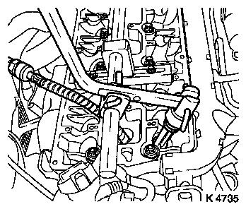
83. Attach toothed belt
- Position toothed belt
- Note: Tensioned side must be taut (I)
|
|
|
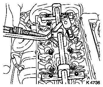
84. Tension toothed belt
- Tension toothed belt tension roller
- Turn adjusting eccentric in direction of arrow (anticlockwise)
until pointer of the toothed belt tension roller is located just
before left stop
- Fasten toothed belt tension roller bolt (1)
|
|
|
85. Remove KM-852
86. Timing, Check
- Turn crankshaft (720°)
- At crankshaft ribbed V-belt pulley bolt
- Note: In direction of engine rotation
- Set crankshaft to mark.
- Note: Marks on drive gear toothed belt and rear toothed belt
cover must align (III)
- Insert KM-852 (II)
- Note: Marks must be opposite one another and aligned with the
top edge of the cylinder head (I)
|
|
|
87. Remove KM-852
88. Toothed Belt Tension, Adjust
- Release toothed belt tension roller
- Turn adjustment eccentric in the direction of the arrow
(clockwise) until pointer (1) is aligned with the notch mark at the
toothed belt tension roller (2).
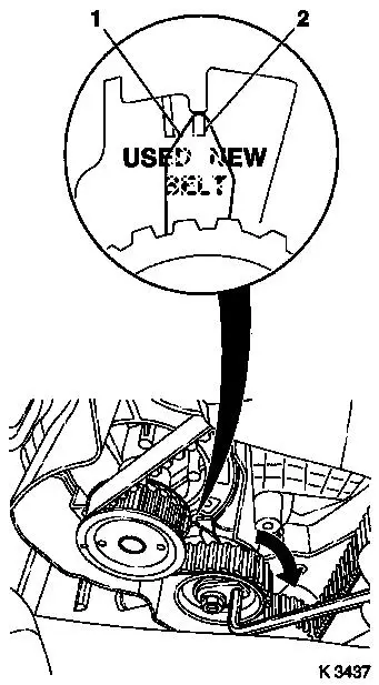
- Adjust used toothed belts to the marking USED
- Adjust new toothed belts to the marking NEW
- Tighten toothed belt tension roller bolt (20 Nm / 15 lbf.
ft.)
|
|
89. Toothed Belt Tension, Check
- Turn crankshaft (720°)
- Note: Pointers on the toothed belt tension roller and notch
mark must align
- Adjust used toothed belts to the marking USED
- Adjust new toothed belts to the marking NEW
90. Clean threads
- Camshaft sensor to cylinder head
91. Install camshaft sensor
- Note: Insert bolts with locking compound
- Tighten bolts (8 Nm / 6 lbf. ft.)
92. Install lower part of toothed belt cover
- Clip to rear of toothed belt cover
- Tighten bolt (4 Nm / 3 lbf. ft)
93. Install upper part of toothed belt cover
- Clip to rear of toothed belt cover
- Tighten bolts (4 Nm / 3 lbf. ft)
|
94. Install cylinder head cover
- Replace gasket (2)
- Apply sealant (1)
- Caution: Complete assembly operations within 10 minutes
- Tighten bolts (8 Nm / 6 lbf. ft.)
- Attach engine vent hose
|
|
95. Connect wiring harness plug of camshaft sensor
- Connect wiring harness plug.
- Clip to bracket
96. Connect wiring harness plug of temperature sensor
97. Install ignition module
- Remove KM-6009
- Tighten bolts (8 Nm / 6 lbf. ft.)
- Connect wiring harness plug.
98. Raise vehicle
99. Install ribbed V-belt tensioner
- Tighten bolt (35 Nm / 26 lbf. ft.)
- Tension ribbed V-belt tensioner.
- Insert KM-6130
100. Attach crankshaft ribbed V-belt pulley
- Insert KM-911
- Replace bolt
- Tighten bolt (95 Nm / 70 lbf. ft. + 30° + 15°.)
- Remove KM-911
- Insert front closure plug
101. Install ribbed V-belt
- Note: Note running direction and installation position
- Release ribbed V-belt tensioner
- Remove KM-6130
102. Install ribbed V-belt cover
- Screw in bolts
- Install clip
103. Lower vehicle
104. Mount right front wheel
105. Lower vehicle
106. Attach front right wheel
- Tighten bolts (110 Nm / 81 lbf. ft.)
107. Install air cleaner housing
- Tighten bolt
- Install suction hose
- Attach engine vent hose
- Clip in tank vent valve
- Connect wiring harness plug.
108. Install engine cover
- Unscrew oil filler pipe cap
- Insert retaining lugs
- Tighten bolts (8 Nm / 6 lbf. ft.)
- Screw on oil filler pipe cap
109. Connect battery
110. Calibrate steering angle sensor
Note: Rotate the
steering wheel one time from its right-hand to its left-hand
stop.
111. Program volatile memories
112. Close bonnet
|
