|
Main Shaft, Disassemble and Assemble (F17+)
Note: Transmission
remains installed.
 Remove Remove
|
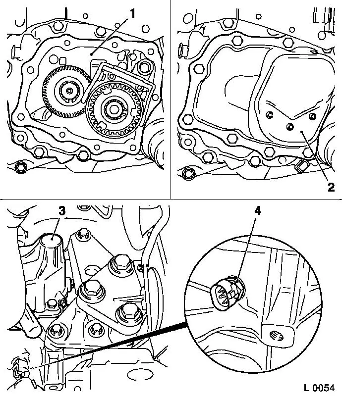
| 1. |
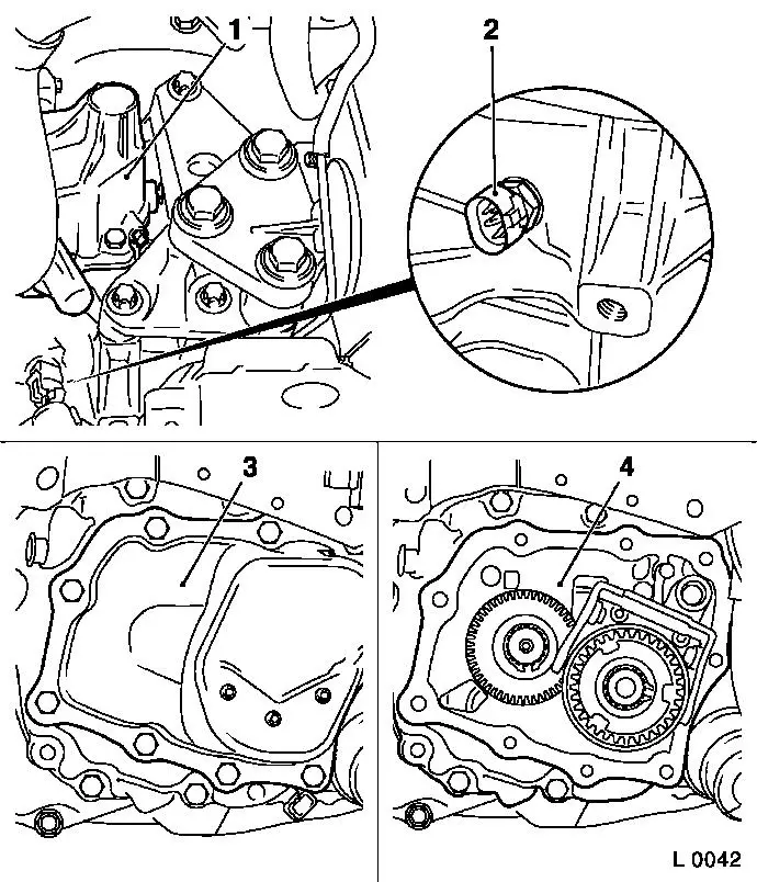
Remove shift mechanism cover (1)
|
| 2. |
Remove reversing lamp switch (2)
| • |
Disconnect wiring harness plug for reversing lamp switch
|
| • |
Unscrew reversing lamp switch
|
|
| 3. |
Remove end shield cover (3)
|
|
|
| 6. |
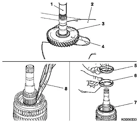
Remove 1st gear gearwheel
| • |
Push 1st gear gearwheel (4) off main shaft with KM-307-B (2) and KM-736
(1)
|
| • |
Remove gear wheel and pressure piece (3)
|
|
| 7. |
Remove 1st gear gearwheel synchro ring
| • |
Remove needle bearing, inner synchro ring (5), intermediate
ring (6) and outer synchro ring (7)
|
|
| 8. |
Remove synchro body retainer
| • |
Remove 1st/2nd gear synchro body retainer with KM-396 (8)
|
|
|
|
| 9. |
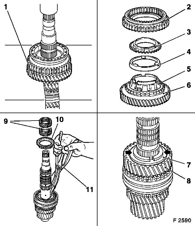
Remove 2ndgear gearwheel
| • |
Push 1st/2nd gear synchromesh body assembly and 2nd gear
gearwheel (1) off main shaft with KM-307-B and KM-736
|
| • |
Remove 1st/2nd gear shift sleeve (2), outer synchroniser ring
(3), intermediate ring (4) and inner synchroniser ring (5) from 2nd
gear gearwheel (6) and needle bearing
|
|
| 10. |
Remove pressure piece halves (arrows)
| • |
Remove pressure piece halves
|
|
| 11. |
Remove 3rd gear gearwheel (8)
|
| 12. |
Remove 3rd/4th gear synchro body retainer
| • |
Remove 2x slotted needle bearing (9)
|
| • |
Remove 3rd gear synchro ring (10)
|
| • |
Remove 3rd/4th gear synchro body retainer with KM-396 (11)
|
| • |
Remove spacer from synchro body
|
|
|
|
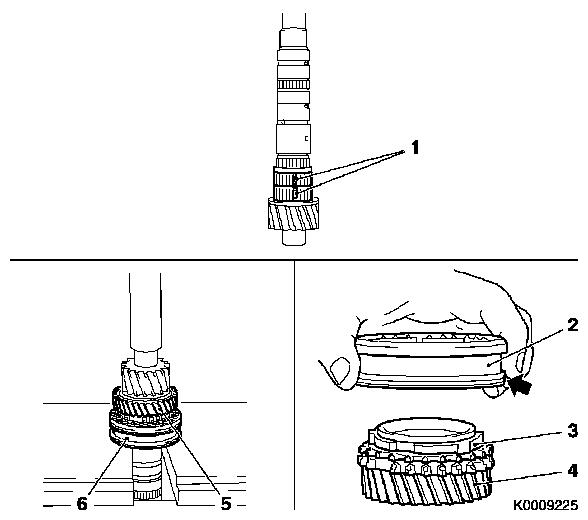
| 13. |
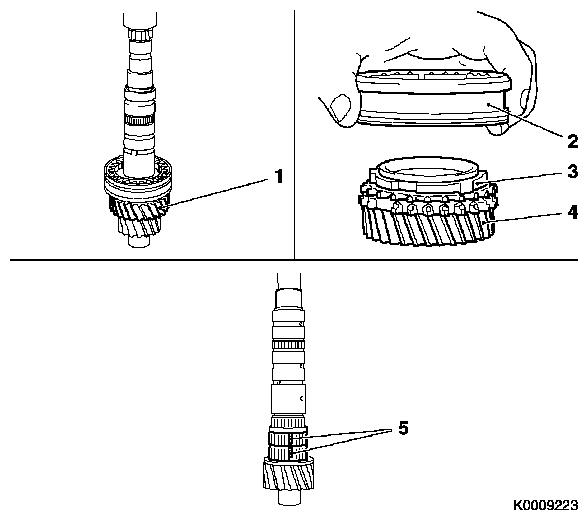
Detach 4th gear gearwheel
| • |
Press of 4th gear gearwheel (4) and synchromesh body with KM-307-B
|
| • |
Take 3rd/4th gear synchro body (2) and 4th gear synchro ring
(3) off 4th gear gearwheel
|
|
| 14. |
Remove needle bearing (5)
| • |
Remove 2x slotted needle bearings from main shaft
Note: Open needle
bearings.
|
|
|
 Install
Important: If gear wheels are
damaged, always inspect the wheels on the gear cluster and replace
this if necessary
|
| 16. |
Inspect parts
| • |
Check all parts for wear, damage and signs of scuffing -
replace if necessary
|
|
Important: Coat the bearing,
running or seating surfaces of rotating parts and surfaces under
pressure with transmission fluid. If a synchro body assembly is
completely dismantled, observe the following procedure for
assembly.
|
| 17. |
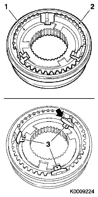
Assemble synchro body
| • |
Insert synchromesh body (1) into shifter collar (2)
|
| • |
Insert 3 thrust pieces (3)
Note: Attach bevel and
then press into synchromesh body assembly.
|
|
|
|
|
| 18. |
Fit needle bearing (1)
| • |
Set 2 slotted needle bearings on main shaft and clip
together
|
|
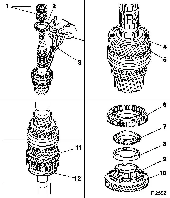
| 19. |
Attach 3rd/4th gear synchro body assembly
Important: Lugs on synchro ring
must be flush with grooves on synchro body
|
| • |
Position 4th gear synchroniser ring (3) and synchromesh body
assembly (2) on 4th gear gearwheel (4)
Note: Groove on sliding
sleeve (arrow) points to 4th gear gearwheel.
|
| • |
Press synchromesh body assembly (6) and 4th gear gearwheel (5)
onto main shaft
|
|
|
|
| 20. |
Attach 3rd gear gearwheel
| • |
Place spacer on synchro body
|
| • |
Fit new retainer with KM-396 (3)
Note: Retainer must be
correctly seated in groove
|
| • |
Place 3rd gear synchro ring (2) on synchro body assembly
|
| • |
Attach 2x slotted needle bearings (1) to main shaft
|
| • |
Place 3rd gear gearwheel (5) on main shaft
|
| • |
Fit both thrust washer halves (arrows) and retaining ring (4)
with grease
|
|
| 21. |
Attach1st/2nd gear synchro body assembly
Important: The lugs on the
synchroniser rings must align with the grooves on the synchromesh
body and the gearwheel.
|
| • |
Set needle bearing on main shaft
|
| • |
Place 1st/2nd gear synchro body assembly (6), with inner
synchro ring (9), intermediate ring (8) and outer synchro ring (7)
on 2nd gear gearwheel (10)
|
| • |
Push 1st/2nd gear synchro body assembly (12) and 2nd gear
gearwheel (11) onto main shaft
|
|
|
|
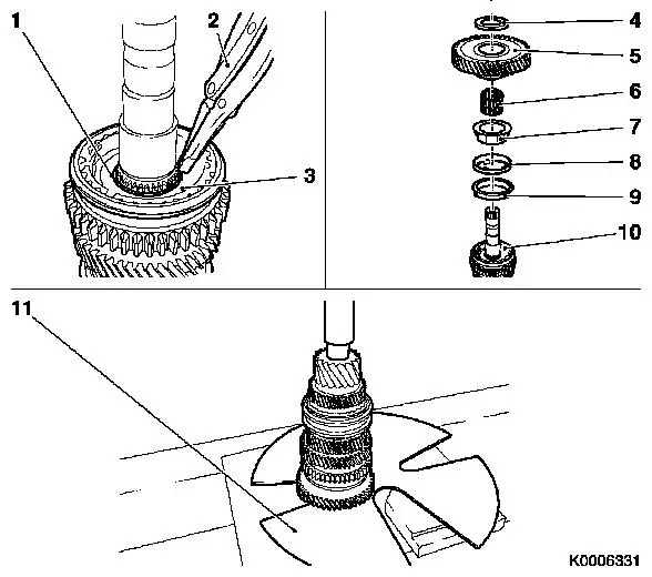
| 22. |
Secure 1st/2nd gear synchro body assembly (3)
| • |
Insert new retainer (1) with KM-396
(2)
Note: Retainer must be
correctly seated in groove
|
|
| 23. |
Attach 1st gear gearwheel (5)
| • |
Place slotted needle bearings (6) on main shaft
|
Important: The lugs on the
synchroniser rings must align with the grooves on the synchromesh
body and the gearwheel.
|
| • |
Place 1st gear gearwheel with inner synchro ring (9),
intermediate ring (8) and outer synchro ring (7) on 1st/2nd gear
synchro body assembly (10)
|
|
| 24. |
Attach 1st gear pressure piece (4)
| • |
Press pressure piece to main shaft with KM-307-B (11)
|
|
|
| 25. |
Visually inspect main shaft
| • |
All gear wheels must rotate freely
|
|
|
| 27. |
Install end shield (1)
Note: Observe the
magnet
|
| 28. |
Install end shield cover (2)
|
| 29. |
Install gearshift cover (3)
|
| 30. |
Transmission Fluid Level, Check and Correct
|
| 31. |
Install reversing lamp switch (4)
| • |
insert with new seal ring
|
| • |
Tighten reversing lamp switch 20
Nm
|
| • |
Connect wiring harness plug
|
|
| 32. |
Check ease of gear shifting
|
|
|
