|
Relay Frame – Engine Compartment Fan Module,
Remove and Install
 Remove Remove
| 2. |
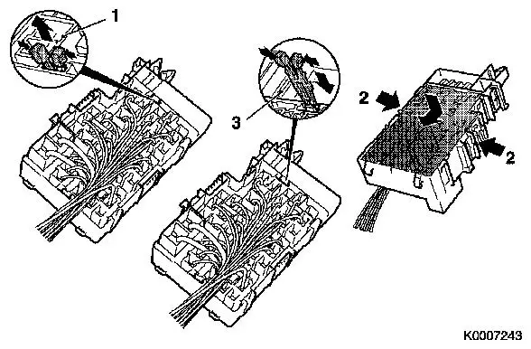
Remove cover, relay box
| • |
Release wiring harnesses as necessary
|
|
|
| 3. |
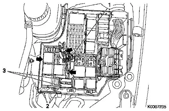
Release wiring harness plug (1) and disconnect
|
| 5. |
Unclip relay frame, engine compartment fan module (arrow)
| • |
Release front wiring harness
|
|
| 6. |
Remove relay frame for engine compartment fan module from relay
box
|
|
|
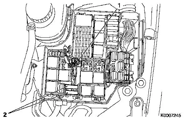
| 7. |
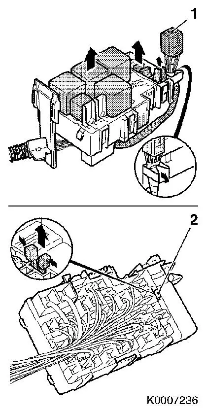
Detach wiring harness with wiring harness plug (1)
|
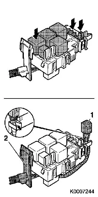
| 8. |
Pull out relay, fuses and fuse puller
|
Important: Note the installation
positions of the relays and fuses
|
| 9. |
Compress housing retainer (2) and remove
|
|
| 10. |
Release secondary retainer
|
|
| 11. |
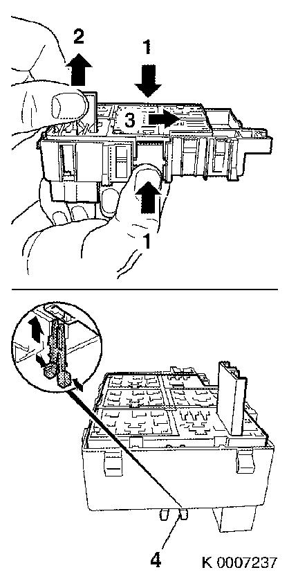
Release housing on both sides (1)
|
| 12. |
Lift housing (2) and slide in direction (3)
|
| 13. |
Secure released housing with housing retainer (4)
Note: For a clearer
illustration, the cables are not shown.
|
|
| 14. |
Transfer wiring harnesses
|
Important: The individual cables
must be replaced in the new housing one by one if possible. If this
is not possible, the cables must be marked correspondingly.
|
| 15. |
The secondary retainer must be released on the new housing
|
| 16. |
The released housing must be secured with the housing
retainer
|
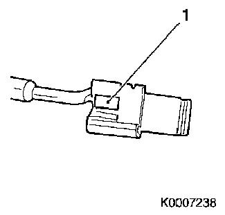
| 17. |
Before inserting into the housing, the spring contacts must be
checked. If necessary, locking mechanism (1) must be corrected
carefully.
|
|
|
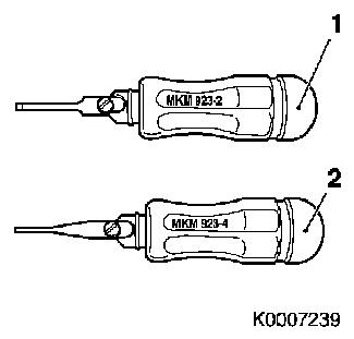
| 18. |
Release tools required:
| 1. |
MKM-923-2 |
| 2. |
MKM-923-4 |
| 3. |
(2) hex screwdriver 2 mm (not shown) or suitable
tool |
|
|
|
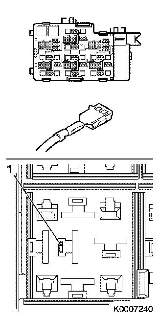
| 19. |
Release locking mechanism of the RT 6.3–contacts with
Special Tool MKM-923-2 and pull out the
contacts
|
| 20. |
The locking mechanism (1) for these contacts is in the
housing
|
|
|
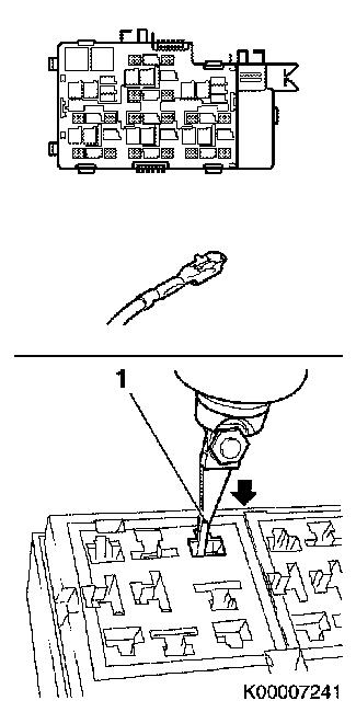
| 21. |
Release locking mechanism of the MP 2.8–contacts with
Special Tool MKM-923-4 and pull out the
contacts
|
| 22. |
The locking mechanisms are on the contacts
|
|
|
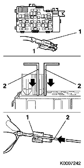
| 23. |
Release locking mechanisms of the Maxi-Power-Timer contacts (1)
with two 2 mm hex screwdrivers (2) and pull out
Note: The two locking
mechanisms are on the sides of the contacts
|
| 24. |
Only one side is depicted in the lower part of the
illustration
|
|
|
|
| 25. |
Insert the contacts that have not yet been inserted into the
chamber of the new housing previously noted
|
| 26. |
Compress head of housing retainer (1) and remove
|
| 27. |
Release secondary retainers (2) and push the upper part into
the limit position, upper and lower part are now flush
|
| 28. |
Secure upper part by inserting the housing retainer (3)
Note: Check correct
seating of all contacts.
|
|
 Install
| 29. |
Insert relay, replacement fuses and fuse puller
|
| 30. |
Attach wiring harness with wiring harness plug (1)
|
| 31. |
Insert relay frame for engine compartment fan module into relay
box, at the same time insert front wiring harness (2)
|
|
|
|
| 32. |
Insert wiring harness plug (1)
|
|
| 34. |
Secure previously released wiring harnesses
|
| 37. |
Program volatile memories
|
| 38. |
Electrical function check
|
|
