When fuel gauge sender or lift pump is renewwed, mate sure replacement parts are compatible (=> version I and II).
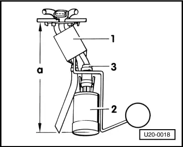
Version I
‒ →
The sender with potentiometer and angle -1- should only be installed with lift pump shown in this illustration -2- (SWF).
Sender installation sequence
‒ Push hose -3- as far as possible onto lift pump connection and secure with hose clip.
‒ →
Push sender supply pipe onto hose -3- until distance a = 175 ± 1mm has been obtained.
Secure hose with a second hose clip.
Notes:
◆ Hose clips must not touch pump contacts.
◆ Ensure that float can move freely.
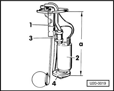
Version II
‒ →
The sender with parallel - mounted potentiometer -1- is only to be used where lift pump shown in illustration -2- (VDO) and strainer -4- are installed.
Sender installation sequence
‒ Push connecting hose -3- as far as possible onto lift pump connection and secure with hose clip.
‒ Push sender supply pipe onto hose -3- until distance a = 175 ± 1mm has been obtained.
Secure hose with a second hose clip.
Notes:
◆ Hose clips must not touch pump contacts.
◆ Ensure that float can move freely.
‒ →
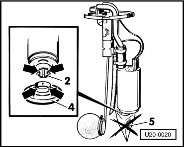
If lift pump is equipped with a filter bag -5-, this should be carefully levered of using a screwdriver.
‒ Push strainer -4- onto lift pump -2- until retaining lugs on strainer are resting against ribs on the pump housing -arrows-.