volkswagen Workshop Repair Guides

Volkswagen Golf Mk1 Workshop Service Manuals & Auto Repair Guides

Rubber mounted steering box > < Repairing steering with telescopic column
Running gear
Repairing steering gear
Renewing or repairing steering box
 
U48-0013

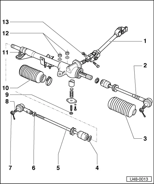
R + I through hole in righthand wheel housing.

Steering box

Before installing a new abox, set it to the central position, => Fig. 1 and screw tie rods on to the correct length, =>Fig. 2

When installing box, insert pinion in universal joint shaft and then place box on studs. After installing, adjust shift linkage bearing plate.

=> Manual gearbox 020; Repair Group 34

Before installing a new box in vehicles with automatic gearbox, bend up tab for shift linkage.

Modification:

From model year 1978 (August 1977), steering wheel mounted in rubber

 
U48-0013
  • Universal joint shaft
    • ◆ To remove, detach box from body and shaft linkage, from box, then pull box off studs.
    • ◆ Watch marks => page 48-8, Fig.3
    • ◆ Installing => page 48-8, Fig. 4
  • Tie rod, fixed
    • ◆ Only the adjust able rod is supplied as a replacement part.
    • ◆ Adjust length => Fig. 3
  • Boot, left
    • ◆ Pull on hand off over tie rod.
    • ◆ Mod: => Fig. 6

Checking adjustment

Steering stiff and does not self-center

  • ‒ Adjusted too tightly.

Steering rattles

  • ‒ Adjusted too loosely, or rattling may be coming from some other location
 
U48-0013
  • Lock nut
  • Tie rod
    • ◆ Adjustable renewing => Fig. 3
  • 50 Nm
  • 30 Nm and turn on to split pin hole
  • Tie rod end
  • Lock nut
    • ◆ Turn adjusting screw in until it touches the thrust washer then hold it in position and tighten lock nut => Figs. 4 and 5
  • Boot, right
    • ◆ Secure to steering box with hose clip, pull on and off over tie rod
    • ◆ Mod: => Fig. 6
 
U48-0013
  • 20 Nmfont=symbol charset=fontspecific code=042)

    font=symbol charset=fontspecific code=042)    Self-locking nut

  • 20 Nmfont=symbol charset=fontspecific code=042)
  • 30 Nm

Note:

Use only special grease Part No. AOF 063 00 04 for steering box.

 
U48-0014

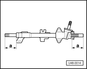
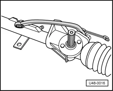
→ Fig.1    Set rack in central position

(Dimension "a" same on each side).

 
U48-0015

→ Fig.2    Screwing tie rods on

Vehicles with manual gearbox:

Screw tie rods on uniformly to give dimension "b" = 69 mm, lock tie rods.

Vehicles with automatic gearbox:

Adjust left to "b" = 69 mm and right to 67 mm. Set tie rod length to 381 mm.

This will ensure adequate clearance between tie rod and automatic gearbox.

Note:

Adjust toe on right hand tie rod.

 
V48-1030

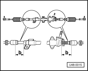
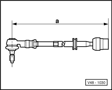
→ Fig.3    Adjusting tie rods

Note:

Only the adjustable tie rod is supplied as a replacement part.

Renewing fixed tie rod

  • ‒ Set steering box in central position and measure distance betwueen tie rod joint and steering box on rod to be renewed.
  • ‒ Set new tie rod to a length for -a- = 379 mm =>Fig. 3
  • ‒ Screw tie rod on to the distance measured and lock it.
  • ‒ Adjust wheel toe on righthand tie rod.

Renewing adjustable tie rod

  • ‒ Set steering box in central position and measure distance between tie rod joint and steering box.
  • ‒ Screw new tie rod on to the same distance and lock it.
  • ‒ Adjust wheel toe on righthand tie rod.
 
U48-0016

→ Fig.4    Adjusting steering box

  • ‒ For loosening and tightening the lock nut use a normal 14 x 17 mm ring spanner.
  • ‒ Warm the spanner just up from the 17 mm end and bend to approx. 25° => Fig. 5.
 
U48-0017

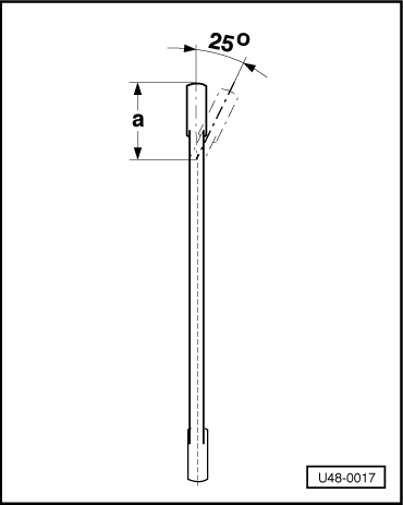
→ Fig.5    Modifying spanner for steering box

-a- = 50 mm

 
U48-0018

→ Fig.6    Boot with retaining ring

From Ch. No 179 3 258 136 or 539 2 033 386 a boot with a wider shoulder at the outer end is fitted. A ring is fitted on this shoulder to prevent the boot from slipping off the holder on the tie rod.

Repair instructions

  • ‒ The new boot can be installed on earlier vehicles.
  • ‒ Take ring off before adjusting the toe and then straighten the boot and fit ring again.
  • ‒ The ends of the ring must be be at the top.

Rubber mounted steering box > < Repairing steering with telescopic column