
Golf Mk3
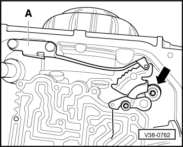
 Note
Note
|
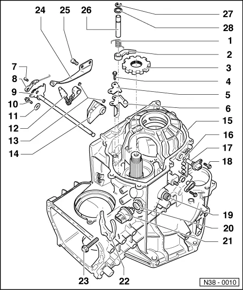
| 1 - | Return spring |
| q | Installing → Fig. |
| 2 - | Detent lever |
| q | Insert with return spring → Fig. |
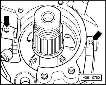
| 3 - | Parking lock gear |
| q | Rounded side faces teeth of pinion shaft |
| 4 - | Bolt, 14 Nm |
| 5 - | Support plate |
| q | Installing → Fig. |
| 6 - | Guide plate |
| q | Insert before support plate → Fig. |
| 7 - | Bolt, 3.5 Nm |
| 8 - | Spool valve actuator |
| q | Adjusting → Chapter, Removing and installing valve body |
| 9 - | Selector shaft with selector segment |
| 10 - | Bolt, 10 Nm |
| 11 - | Lock washer |
| 12 - | Engaging lever |
| q | Insert together with selector shaft and detent segment |
| 13 - | Spring pin |
| q | Drive in after inserting engaging lever and detent segment → Fig. |
| q | Drive out with a drift |
| 14 - | Detent segment |
| q | Insert together with selector shaft and engaging lever |
| 15 - | Gearbox housing |
| 16 - | O-ring |
| q | Always renew |
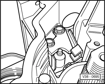
| 17 - | Vehicle speed sender -G68- |
| q | Checked in vehicle through self-diagnosis → Chapter |
| 18 - | Bolt, 10 Nm |
| 19 - | Seal |
| q | Lever out with a screwdriver |
| q | Drive in flush using tube -VW 423- |
| 20 - | O-ring |
| q | Always renew |
| 21 - | Multifunction switch -F125- |
| q | Insert so that 1 pin each is resting on a slope of the detent segment |
| q | Checked in vehicle through self-diagnosis → Chapter |
| 22 - | Retainer |
| q | For multifunction switch -F125- |
| 23 - | Bolt, 10 Nm |
| 24 - | Spring for selector segment |
| 25 - | Bolt, 10 Nm |
| 26 - | Shaft for detent lever |
| q | Secured by retaining ring and bearing cap of pinion shaft |
| q | Depending on design, with groove for retaining ring |
| 27 - | Retaining ring |
| q | Always renew |
| q | Install only on shafts with groove for retaining ring |
| 28 - | Washer |
Note
|
|
|
|
|
|