volkswagen Workshop Repair Guides

Volkswagen Workshop Service and Repair Manuals

Unscrewing control unit from hydraulic unit > < Connecting brake lines from brake master cylinder to hydraulic unit
Removing control unit and hydraulic unit
   
Removing control unit and hydraulic unit
Special tools and workshop equipment required
t  Torque wrench -V.A.G 1331-
t  Torque wrench -V.A.G 1410-
t  Brake pedal depressor -V.A.G 1869/2-

   
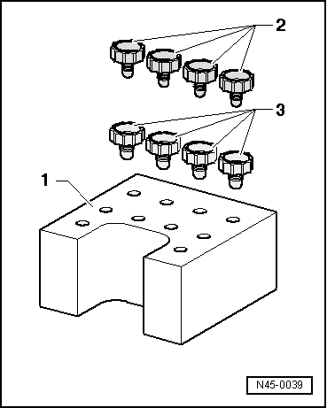
Sealing plugs from repair kit, part number 1 H0 698 311 A
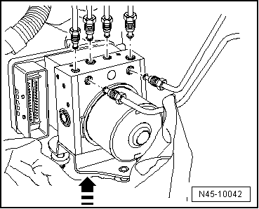
The transport protection for the contact pins must always be placed on the hydraulic unit after the control unit has been disconnected from the hydraulic unit.
No warranty can be assumed for hydraulic units without transport protection.
1 - Transport protection for contact pins (foam)
2 - Sealing plug M10
3 - Sealing plug M12
Removing
Location:
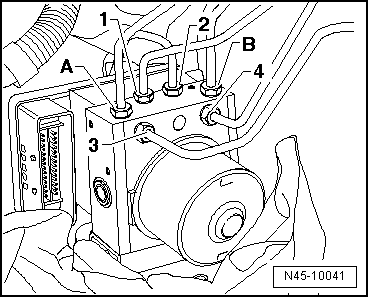
The control unit is bolted to the hydraulic unit and is located on right in the engine compartment.
  WARNING
Do not bend the brake lines in the area of the hydraulic unit!
–  Read out and note the existing control unit code.
–  Note or request radio code on vehicles with coded radio if necessary.
–  Disconnect battery → Electrical system; Rep. gr.27.
–  Remove engine cover panel.
Additional work on following engines:
1.4 l/59 kW TSI engine:
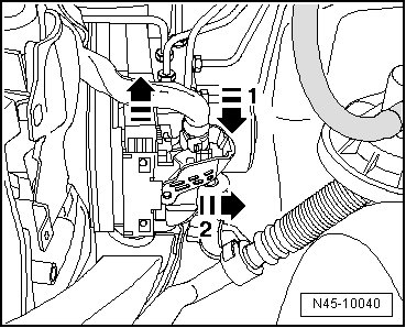
–  Pull hose off non-return valve.
–  Pull air filter housing upwards off mountings and place aside → 4-cyl. injection engine (1.4 l engine); Rep. gr.24.
1.6 l/75 kW engine:
–  Remove upper part of intake manifold → 4-cyl. injection engine (1.6 l engine, roller rocker finger); Rep. gr.24.
1.4 l/118 kW TSI engine:
–  Clamp off hose from coolant expansion tank and pull it off.
–  Remove pressure pipe and inlet connection with regulating flap control unit → 4-cylinder injection engine (1.4 l direct injection engine, turbocharger and compressor); Rep. gr.24.
–  Remove charge air hose and charge air pipe and lay aside → 4-cylinder injection engine (1.4 l direct injection engine, turbocharger and compressor); Rep. gr.21.
Diesel engine with or without diesel particulate filter:
–  Remove plenum chamber cover → General body repairs, exterior; Rep. gr.50.
–  Remove plenum chamber bulkhead → General body repairs, exterior; Rep. gr.50.
Diesel engines with diesel particulate filter:
–  Unscrew exhaust gas pressure sensor 1 -G450-, separate electrical connectors, unscrew and lower diesel particulate filter → Rep. gr.26.
Continuation for all models:
  N45-0039
–  Release connector on control unit in direction of arrow -1- and pull off -2-.
–  Apply brake pedal depressor -V.A.G 1869/2-.
–  Connect bleeder bottle hose to front left brake caliper bleeder valve and rear left brake caliper bleeder valve and open bleeder valves.
–  Depress brake pedal at least 60mm using brake pedal depressor -V.A.G 1869/2-.
–  Close front left and rear left bleeder valve.
–  Do not remove brake pedal depressor -V.A.G 1869/2-.
–  Place sufficient lint-free cloths under the control unit and hydraulic unit.
Ensure no brake fluid gets onto contacts.
  N45-10040
–  First identify the two brake master cylinder brake lines -A and B- and unscrew from the hydraulic unit.
–  Immediately seal brake lines and threaded holes with sealing plugs from repair set Part No. 1H0 698 311 A.
–  Identify brake lines (brake calipers) -1 to 4-, unscrew and seal.
  N45-10041
–  Pull hydraulic unit with control unit upwards out of dampers.
  N45-10042

Unscrewing control unit from hydraulic unit > < Connecting brake lines from brake master cylinder to hydraulic unit