volkswagen Workshop Repair Guides

Volkswagen Workshop Service and Repair Manuals

Climatronic - passenger compartment > < Connectors on Climatronic control unitJ255
Pin assignment for multi-pin connectors A, B and C on back of Climatronic control unitJ255
Pin assignment for multi-pin connectors A, B and C on back of Climatronic control unit -J255-
Special tools and workshop equipment required
t  Test box -V.A.G 1598/42-
   
t  Adapter cable -V.A.G 1598/47-
t  Template -1598/47-2-
  W00-10003
20-pin connector, connector housing -A-, T20c in current flow diagram
1 - Sunlight penetration photosensor 2 -G134- or sunlight penetration photosensor -G107-, signal
2 - 
3 - Sunlight penetration photosensor 2 -G134- or sunlight penetration photosensor -G107-, signal
5 - High-speed CAN bus
6 - Low-speed CAN bus
9 - + 5 V for sunlight penetration photosensor 2 -G134- or sunlight penetration photosensor -G107-
10 - Heated driver seat regulator -E94- (optional)
11 - Heated front passenger seat regulator -E95- (optional)
12 - Terminal 75 (optional)
13 - Left vent temperature sender -G150- (from January 2004)
14 - Right vent temperature sender -G151- (from January 2004)
16 - Terminal 30a/terminal 15
17 - Signal earth for sunlight penetration photosensor -G107-, sunlight penetration photosensor 2 -G134-, left vent temperature sender -G150- and right vent temperature sender -G151-.
18 - Air conditioner compressor regulating valve -N280-
19 - Terminal 31
20 - Terminal 30a/terminal 15
  N87-10777
16-pin connector, connector housing -B-, T16c in current flow diagram
1 - + 5V for control motors
2 - Potentiometer for left temperature flap control motor -G220-
3 - Potentiometer for right temperature flap control motor -G221-
4 - Potentiometer for defroster flap control motor -G135-
5 - Potentiometer for centre flap control motor -G112-
6 - Potentiometer for air recirculation flap control motor -G143- (to December 2003) potentiometer for temperature flap control motor -G92- (from January 2004)
7 - Potentiometer for air flow flap control motor -G113-
8 - Left footwell vent temperature sender -G261-
9 - Right footwell vent temperature sender -G262-
10 - Fresh air intake duct temperature sensor -G89- (to September 2005)
11 - Evaporator temperature sensor -G308- or evaporator output temperature sender -G263-
14 - Signal earth, potentiometer
15 - Left vent temperature sender -G150- (to December 2003)
16 - Right vent temperature sender -G151- (to December 2003)
  N87-10777
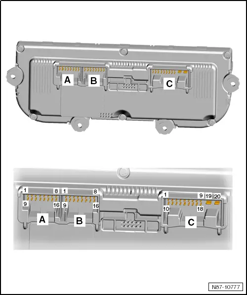
16-pin connector, connector housing -C-, T16k in current flow diagram
1 - Left temperature flap control motor -V158-, cold
2 - Left temperature flap control motor -V158-, warm
3 - Defroster flap control motor -V107-, closed
4 - Defroster flap control motor -V107-, open
5 - Central flap control motor -V70-, chest
6 - Central flap control motor -V70-, footwell
7 - Fresh air and air recirculation flap control motor -V154-, activation of air recirculation mode (up to December 2003), air recirculation flap control motor -V113- (from January 2004), control motor discontinued (from June 2007); function via fresh air/recirculated air, air flow flap control motor -V425- and kinematic mechanism
8 - Fresh air and air recirculation flap control motor -V154- fresh air actuated (to December 2003), air recirculation flap control motor -V113- (from January 2004)
9 - Air flow flap control motor -V71-, open (to May 2007)
10 - Air flow flap control motor -V71-, closed (to May 2007)
11 - Right temperature flap control motor -V159-, cold
12 - Right temperature flap control motor -V159-, warm
15 - Fresh air blower control unit -J126-
16 - Fresh air blower control unit -J126-, signal
  N87-10777

Climatronic - passenger compartment > < Connectors on Climatronic control unitJ255