
Cooling
- Make
- Volvo
- Model
- V60 Factory Service Manual
- Year
- 2011–2016
- Section
- 09 Miscellaneous › Design and Function › Cooling
Cooling
Cooling of control modules for electric operation
The cooling loop for the control modules, which electrically consists of a coolant pump and two valves, is controlled and monitored by the Engine Control Module (ECM).
The following components are cooled using this cooling loop:
- DC to DC Converter Control Module (DCDC)
- On-Board Charger Module (OBC)
- Inverter System Controller ISC
- Electric rear axle ERAD
- Integrated Starter Generator ISG
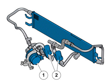
- Coolant pump
- Shut-off valve, cooling (three-way valve)
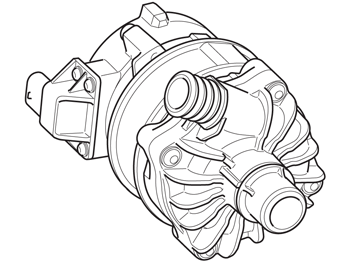
- Coolant pump
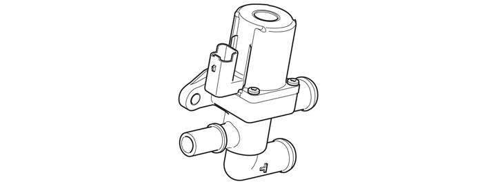
- Shut-off valve, cooling
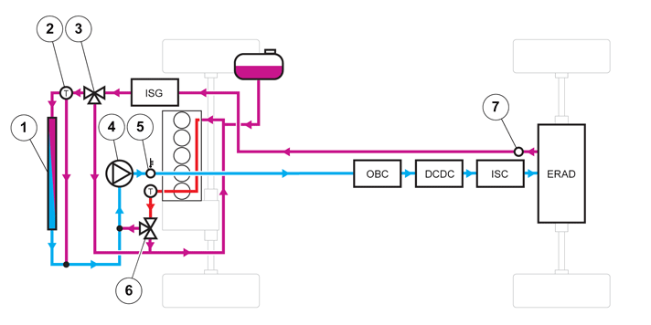
- Low temperature radiator (LTR)
- Hybrid thermostat
- Shut-off valve, cooling A
- (1) Active - Flow to engine
- (0) Inactive - Flow to radiator
- Coolant pump
- Temperature sensor for low temperature section
- Shut-off valve, cooling B
- (1) Active - Flow to T-connection/Water pump
- (0) Inactive - Flow to lower radiator hose
- Drainage plug
Cooling of components that are unique for electrical operation are cooled via the engine's cooling system
Normal flow at low temperature - Equalization mode
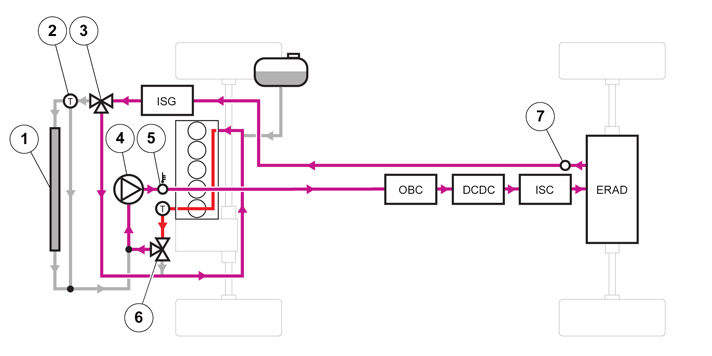
In this mode, the flow goes through the pump to the control modules for electrical operation, back and through the Integrated Starter Generator (ISG), which is located on the engine. Then through valve A and on through the engine and back to the pump again. In this mode, the coolant only circulates, without going through any radiators. This mode is only possible at low temperatures to equalize the temperature between the engine and hybrid components.
Normal flow without passing through the engine
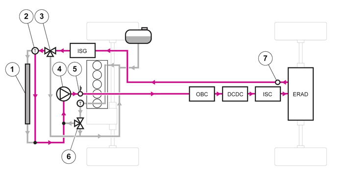
In this mode, valve A is deactivated so that the coolant does not pass through the engine. The coolant instead passes through the hybrid thermostat, which still has not opened. Then through the pump and back to the Integrated Starter Generator (ISG). The thermostat opens at about 20-30 °C.
Cooling mode maximum cooling
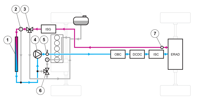
In this mode, control is the same as in the previous mode. The difference is that now the hybrid thermostat has opened and controls the coolant through the radiator. The thermostat opens at approx. 20-30 °C.
High voltage battery cooling
The cooling loop for the high voltage battery, which electrically consists of two coolant pumps and a valve, is controlled and monitored by the Battery Energy Control Module (BECM).
The following components are cooled using this cooling loop:
- High voltage battery
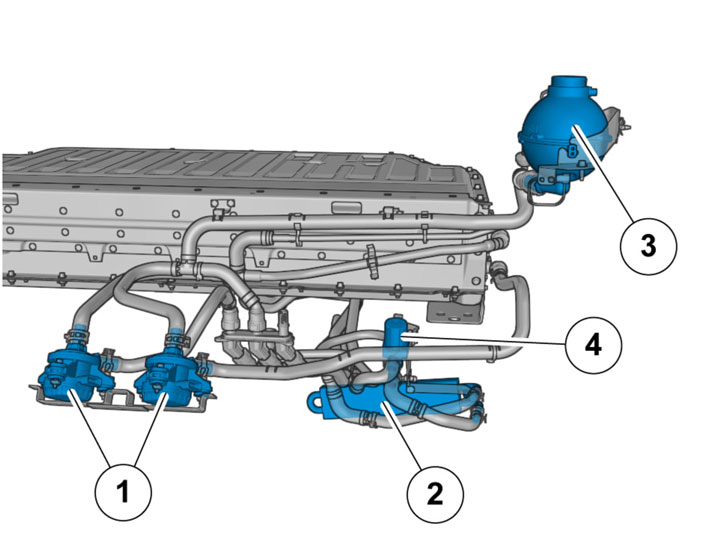
- Battery coolant pump A and B
- Battery radiator
- Battery cooling, level sensor expansion tank
- Battery cooling, shut-off valve
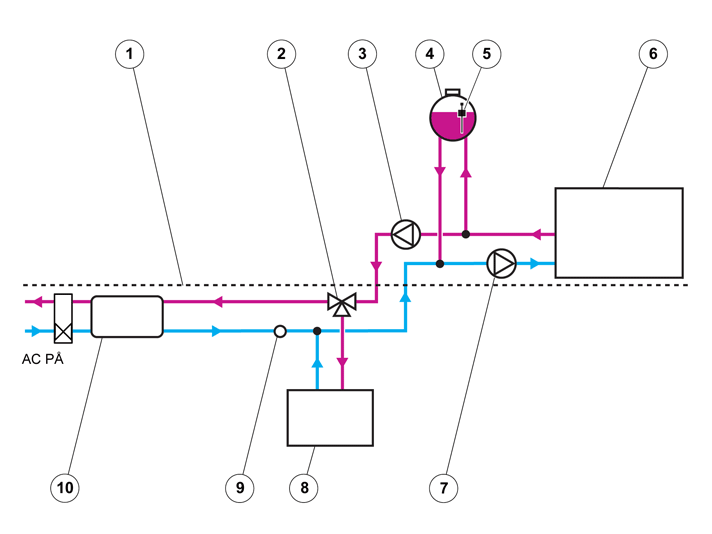
- floor
- Shut-off valve, battery cooling
- Battery coolant pump B
- Expansion tank
- Battery cooling, level sensor expansion tank
- High voltage battery
- Battery coolant pump A
- Battery radiator
- Drainage plug
- Heat exchanger/Chiller
The cooling system has two pumps and a valve that control the flow in the different cooing modes. There is a radiator under the vehicle on the right-hand side. There is also a heat exchanger that is cooled via the vehicle's electric A/C system.
Equalization mode
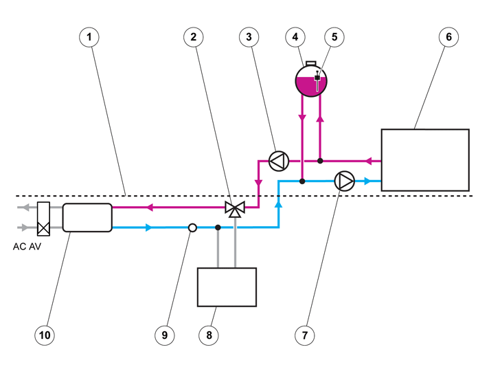
In this mode, which is the normal mode (valve inactive), the coolant only circulates from pump B through the valve and heat exchanger. Then through pump A and through the high voltage battery. No cooling from the A/C system. this is an equalization mode where the temperature is equalized in the system. When the temperature reaches 26°C, the valve closes and routes the coolant through the radiator instead.
Intermediate cooling mode
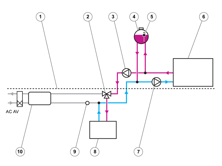
In this mode, the valve is activated and cooling is taken from the radiator under the vehicle. This is an intermediate mode where maximum cooling performance is not required. The valve closes when the temperature reaches 26 °C.
Maximum cooling
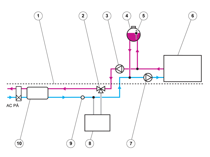
In this mode, the coolant circulates from pump B through the valve and heat exchanger. Then through pump A and through the high voltage battery. Cooling from the A/C system. This occurs when the temperature reaches 32 °C.
Parts & tools for this job For 2011 Volvo V60
- TOOLTorque wrenchSearch: 3/8 inch torque wrench
- TOOLSocket setSearch: socket set metric
- BOOKHaynes manualSearch: Haynes manual Volvo V60
Links open Amazon search results in a new tab. As an Amazon Associate I earn from qualifying purchases.