
Transmission – Design
- Make
- Volvo
- Model
- V60 Factory Service Manual
- Year
- 2011–2016
- Section
- 09 Miscellaneous › Design and Function › Transmission – Design
Transmission – Design
Transmission general
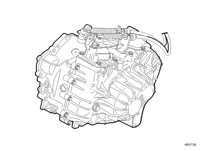
M66 is a six gear manual transmission. All gears, including back-up (reverse), are synchronized. The transmission is intended to be part of a transverse drive line with front wheel or four wheel drive.
The transmission is built together with the final driven in a common aluminum housing. This unique construction makes the transmission very compact while enabling it to transmit high torque.
The engine and transmission have damped mountings, either on the side members with pendulum mounting or on a sub frame.
The transmission and final drive are extremely compact. For further information about dimensions, see Specifications, transmission.
The oil is synthetic and does not normally need to be changed. The oil is heat resistant and tolerates high loads. The hole in the level plug is used to top up the oil and check its level. The oil is drained through the drain plug in the base of the transmission.
The gear wheels are located on four shafts. They are:
- input shaft (A)
- intermediate shaft 1-2, 5-6 (B)
- intermediate shaft 3-4 (C)
- back-up (reverse) shaft (D).
The clutch gears are welded directly to the idler wheel to shorten the length of the shaft. To further shorten the length of the transmission, needle bearing with inner rings are used instead of snap rings.
The inner rings sit on the shaft inside the idler gears and extend lengthwise a little outside each idler gear. When the components on the shafts are pulled together the inner rings counterhold, so that the idler wheels have the clearance that they require to rotate.
The components of the input shafts are pulled together with a bolt located in the end of the shaft. Components of intermediate shaft 3-4 are held together with a press joint and a bolt located in the end of the shaft. The components of intermediate shaft 1-2, 5-6 are held together with the press joint of the 5th and 6th gear pinion.
Transmission, internal components
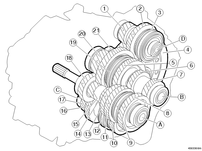
| Position | Component | Located on | |
|---|---|---|---|
| 1 | Final drive gear back-up (reverse) | D | Back-up (reverse) shaft |
| 2 | Idler wheel, back-up (reverse) gear | D | Back-up (reverse) shaft |
| 3 | Back-up (reversing) gear coupling sleeve | D | Back-up (reverse) shaft |
| 4 | Ring gear | Differential | |
| 5 | 2nd gear idler wheel | B | Intermediate shaft 1-2, 5-6 |
| 6 | 5th gear gear wheel | B | Intermediate shaft 1-2, 5-6 |
| 7 | 6th gear gear wheel | B | Intermediate shaft 1-2, 5-6 |
| 8 | Idler wheel for 6th gear | A | Input shaft |
| 9 | Coupling sleeve for 5th-6th gear | A | Input shaft |
| 10 | 4th gear idler wheel | C | Intermediate shaft 3-4 |
| 11 | 5th gear idler wheel | A | Input shaft |
| 12 | 3rd-4th gear coupling sleeve | C | Intermediate shaft 3-4 |
| 13 | 4th gear gear wheel | A | Input shaft |
| 14 | 2nd gear gear wheel | A | Input shaft |
| 15 | 1st gear gear wheel | A | Input shaft |
| 16 | 3rd gear idler wheel | C | Intermediate shaft 3-4 |
| 17 | Final drive gear wheel, 3rd - 4th gear | C | Intermediate shaft 3-4 |
| 18 | 3rd gear gear wheel | A | Input shaft |
| 19 | 1st-2nd gear coupling sleeve | B | Intermediate shaft 1-2, 5-6 |
| 20 | Final drive gear wheel, 1-2, 5-6 | B | Intermediate shaft 1-2, 5-6 |
| 21 | 1st gear idler wheel | B | Intermediate shaft 1-2, 5-6 |
Gear selector, internal
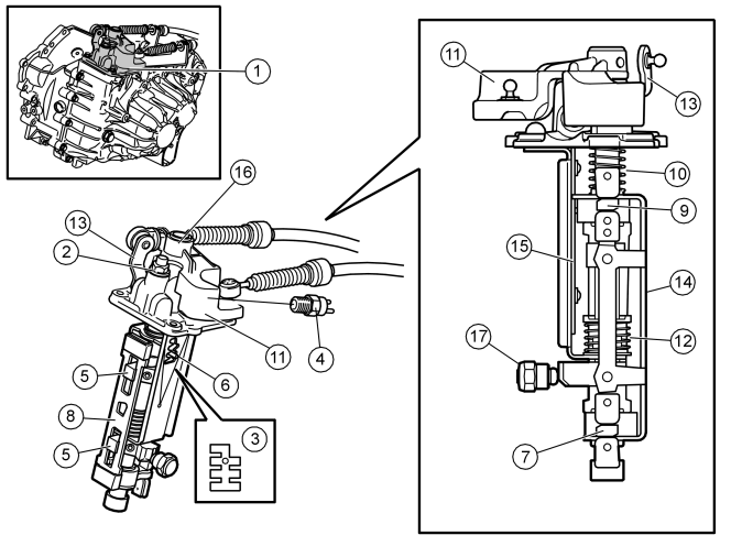
| Position | Component | Position | Component |
|---|---|---|---|
| 1 | Complete control unit | 10 | Spring |
| 2 | Ball limiter, 5-6 control | 11 | Lever for lengthwise movement |
| 3 | Gearshift gate | 12 | Spring |
| 4 | Back-up (reversing) lamps switch | 13 | Lever for lateral movement |
| 5 | Flange | 14 | Catch plate |
| 6 | Gearshift gate pin | 15 | Carrier plate |
| 7 | Lower gear selector | 16 | Bleed cap |
| 8 | Gear selector rod | 17 | Ball limiter for gear selector |
| 9 | Upper gear selector |
The gear selector is in a single complete unit with the exception of the ball limiter for the gear position. This is threaded in the transmission housing. The gear selector is held in position by 4 screws. 2 guide pins in the control housing and a needle bearing in the bottom of the gear selector unit control the position in the transmission housing.
Back-up (reverse) gear in the gear selector assembly is furthest to the right and down. Neutral is between 3rd and 4th.
The back-up (reversing) lamp switch is in the control housing and is affected by the shaft for lateral movement. The back-up (reversing) lamp switch is directly connected to the central electronic module (CEM).
The gear selector unit must not be dismantled. In the event of a fault the whole gear selector unit must be replaced.
4 gear selector forks transfer the movement from the control to the relevant coupling sleeve.
Gear selector assembly and mechanical transmission cables
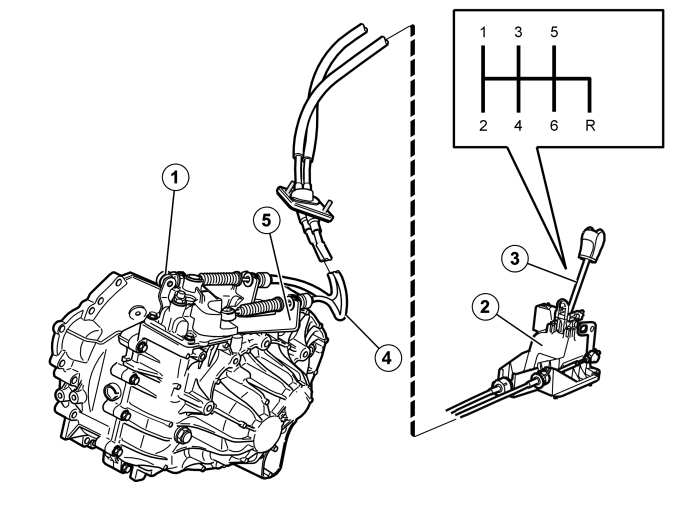
- Locking the adjustable mechanical transmission cable for lateral travel
- Solenoid
- Gear selector assembly
- Mechanical cables
- Mechanical cables bracket.
The mechanical cables are in a cable assembly. In the event of a fault or damage with any of these the whole mechanical cable assembly must be replaced.
The cable sleeves are secured using quick connectors in the gearshift assembly and in the cable bracket on the transmission.
The mechanical transmission cable for lateral travel is adjustable lengthwise. The adjuster is positioned on the mounting towards the lever on the transmission (1).
The gear selector assembly is made of plastic. It has rubber feet (to reduce noise and vibration).
The gear selector assembly has a lever and a lever arm. There is a return spring on the lateral movement lever.
Back-up (reverse) inhibitor
The shift lever assembly houses a solenoid that serves as an electronically controlled reverse inhibitor.
There is an electronic damping function on the solenoid which gives the solenoid a soft action. This reduces noise. The solenoid can be replaced.
Differential
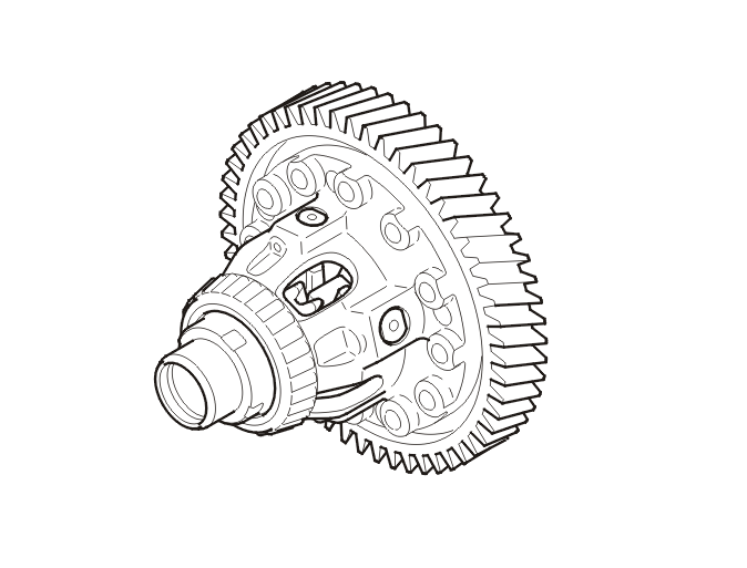
The differential distributes drive shaft torque equally between the drive wheels, even if they are rotating at different speeds.
The differential consists of the differential housing, large and small side gears, shaft journals and thrust washers.
Applies to AWD
On the M66 AWD a sleeve for power transfer is located on the differential.
Synchronization
The synchronizing hub assembly consists of a coupling sleeve, flange and the hub. Each synchronizing hub is joined to its shaft by splines and rotates with it.
There are idler wheels on both sides of each synchronizing hub. The idler wheels rotate freely on the shaft (does not apply to reverse gear). Each idler wheel is constantly engaged in its pinion. The synchronizing set is positioned between the synchronizing hub and the idler wheel.
The synchronizing units are positioned on the shafts in the transmission as follows:
- The synchronizing unit for 1st - 2nd gear is on the intermediate shaft 1-2, 5-6
- The synchronizing unit for 3rd - 4th gear is on the intermediate shaft 3-4
- 5th-6th the synchronizing unit is on the input shaft
- the synchronizing unit for back-up (reverse) gear is on the back-up (reverse) shaft.
The synchronizing rings expand when heated by the same amount as the components they are in contact with. As a result no safety margin is required to counter expansion.
The idler wheels for single and double synchronization have no cones. An inner ring on the synchronizer unit performs this function instead.
The synchronizer unit is a modular system. This makes it easy to upgrade from a single synchronizer to double synchronization by replacing the synchronizer kit.
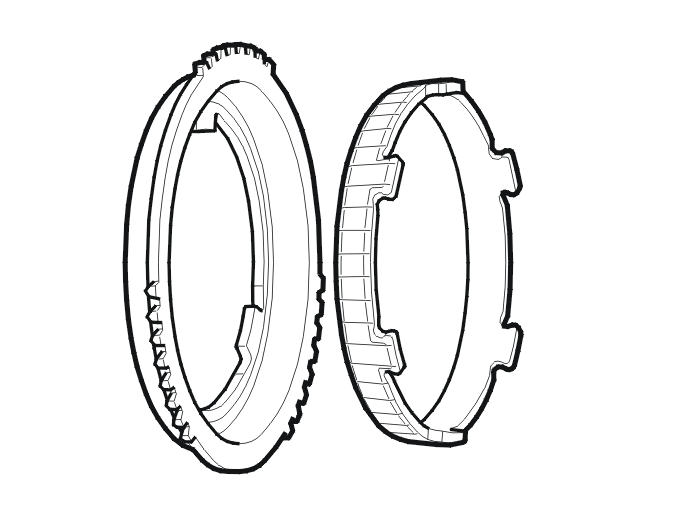
Single synchronization, which has one friction surface, is on:
- back-up (reverse) gear
- 4th gear
- 5th gear
- 6th gear.
The outer ring (to the left in the illustration) is manufactured in pressed steel. The inner ring is pressed steel and the friction surface is coated with sintered brass.
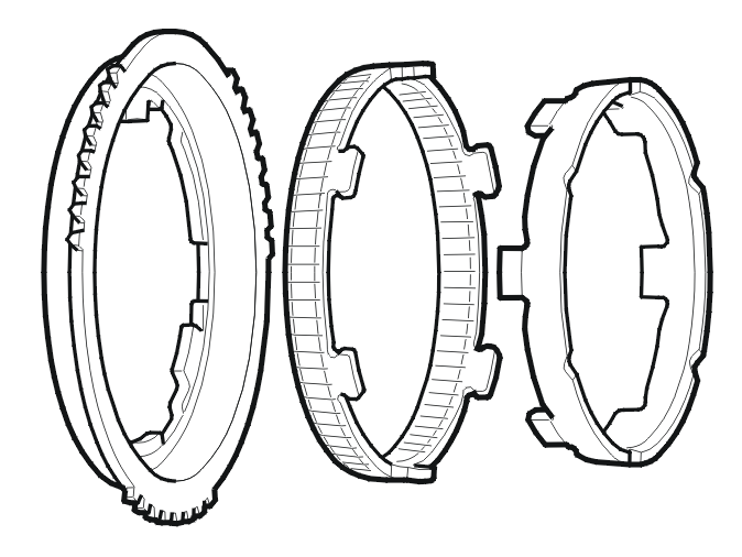
Double synchronization, two friction surfaces, is on:
- 3rd gear.
The outer ring (to the left in the illustration) is manufactured in pressed steel. The sealing ring is pressed steel and the friction surfaces are coated with sintered brass. The inner ring is machined steel.
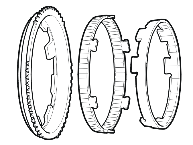
Triple synchronization, three friction surfaces, is on:
- 1st gear
- 2nd gear.
The outer ring (left in the illustration) is made of pressed metal. The intermediate ring is made of pressed metal with a sintered brass coating on the friction surfaces. The inner ring is of pressed metal with a sintered brass coating on the inner friction surface. Triple synchronization also includes a ring integrated with the idler wheel.
Clutch, general
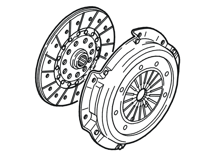
The main task of the clutch system is to transfer torque, disengage during shifting, allow comfortable starting and to act as an efficient vibration damper to eliminate noise and vibration in the chassis and drive train.
The clutch is located between the engine and the transmission. The main components are a pressure plate and a clutch driven plate. The clutch is used to connect the torque from the engine to and from the transmission and therefore to drive the wheels.
The clutch is a single disc dry clutch. The clutch disc is connected to the transmission input shaft on the transmission.
On vehicles with more powerful engines, self-adjusting clutches are used to lower the engagement forces.
Hydraulic clutch control mechanism with concentric slave cylinder (CSC)
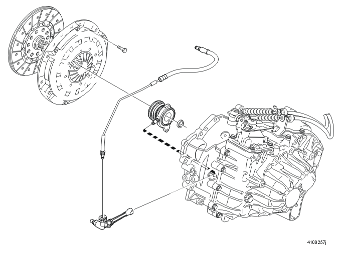
The clutch control mechanism is fully hydraulic. The slave cylinder is inside the clutch cover. There is no mechanical transfer (fork) inside the clutch cover from an external slave cylinder.
The concentric slave cylinder (CSC) means that the slave cylinder is integrated with the throwout bearing.
The concentric slave cylinder (CSC) is extremely efficient and reliable and the throwout bearing is accurately centered.
The unit is mounted with a bolt in the gearcase. The bearings and sliding surfaces do not require lubrication. The bearing on the concentric slave cylinder is self-centering to the clutch fan.
The hydraulic line from the master cylinder is connected to the concentric slave cylinder (CSC) via an adapter. There is a bleed nipple on the adapter.
There are ratios built-in to the system to reduce the force required to transfer torque:
- pedal effort
- hydraulic force
- clutch finger force.
The force is reduced from approximately 8600 N at the clutch to approximately 100 N at the pedal.
If the clutch pedal returns too quickly, the drive line could be damaged by the high torque. There is a shock load limiter in the clutch to avoid this. The shock load limiter chokes the flow between the concentric slave cylinder (CSC) and the master cylinder if there is a danger of the excessive torque. The shock load limiter is in the concentric slave cylinder.
Shock load limiter
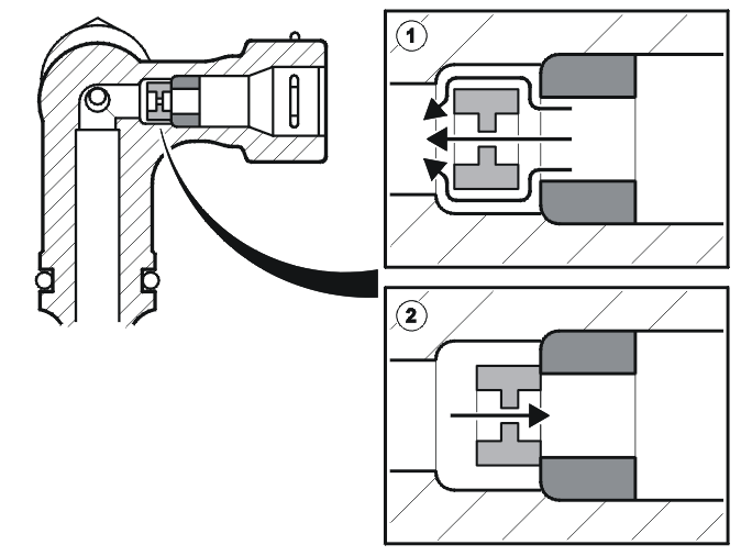
In vehicles with engines with high engine torque the return time of the clutch pedal may be too short. This means that the torque peak is so high that it can damage the driveline.
In the event of the torque peak being to high, the hydraulic flow in the engagement direction is choked between the concentric slave cylinder (CSC) and the master cylinder using a shock load limiter.
Self-adjusting clutch (SAC)
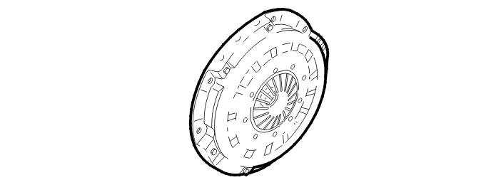
A self-adjusting clutch (SAC) eliminates problems both in terms of wear in the clutch cover and the need for increased force at the pedal as the facing thickness reduces.
This considerably increases the life of the clutch. A self adjusting clutch will not normally require replacement during the lifetime of the vehicle.
A self-adjusting clutch (SAC) senses the increase in release load at the diaphragm spring. It has a adjustment mechanism between the diaphragm spring and the clutch housing. This maintains the position of the diaphragm spring and ensures that the pedal effort required remains constant throughout the service life of the vehicle.
The pressure plate is of the diaphragm spring type. Unlike a traditional type, the pressure plate contains an adjustment ring made of steel or plastic. If there is wear, the adjustment ring moves slightly to maintain the engagement position of the clutch.
The fact that the fingers are unable to move backwards has the following advantages:
- increased wear capacity
- the clutch cover can be made shorter because space is not required for rearward movement of the diaphragm spring.
Clutch driven plate
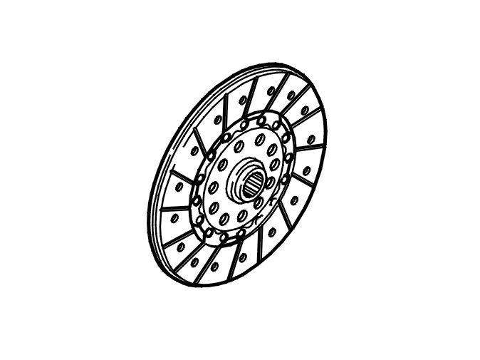
The clutch driven plate is the component that transfers the torque to the input shaft and into the transmission.
The clutch driven plates of today do not have dampers or friction elements. These functions are integrated in the dual mass flywheel.
The clutch driven plate center is greased internally when the clutch driven plate is installed at the factory. This reduces the friction between the clutch driven plate and the input shaft to make shifting easier.
When replacing the clutch driven plate, the input shaft must be lubricated. See the instructions for replacing the clutch.
Dual mass flywheel
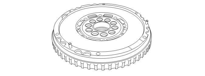
The dual mass flywheel reduces noise from the transmission and improves drivability.
The dual mass flywheel helps reduce the load on the crankshaft bearings. It also improves shift quality because the flywheel mass on the clutch driven plate is lower.
The components of the dual mass flywheel can rotate in relation to one another. This twisting depends on the load from the engine. Twisting of a dual mass flywheel is up to 60 degrees in both directions. You can feel a certain twisting between the components if you turn a dual mass flywheel.
Transmission, general
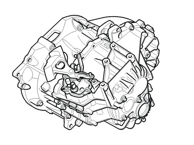
MMT6 is a six shift manual transmission. All gears, including back-up, are synchronized. The synchronizing units, interlock ball, springs and sliding block make up a single unit. This design facilitates service work on the synchronizing unit.
The transmission is intended to be part of a transverse drive line with front wheel drive.
The transmission and final drive are constructed together in a common housing made of aluminum. The transmission is very compact. The transmission is a "light weight model" within its class and weighs 52.5 kg (115.7 lbs) without fluid.
The transmission has a maximum torque transfer of 350 Nm.
The transmission fluid is synthetic and does not normally need to be changed. The oil is heat resistant and tolerates high loads. Fluid is topped up via the filler pipe. The fluid is checked via the level plug. The fluid is drained through the drain plug in the base of the transmission.
The gear wheels are located on three shafts.
- One input shaft, the primary shaft
- Two output shafts, the upper and lower secondary shafts.
The transmission housing only has a sealing ring. The seal consists of a liquid gasket.
Transmission, internal components
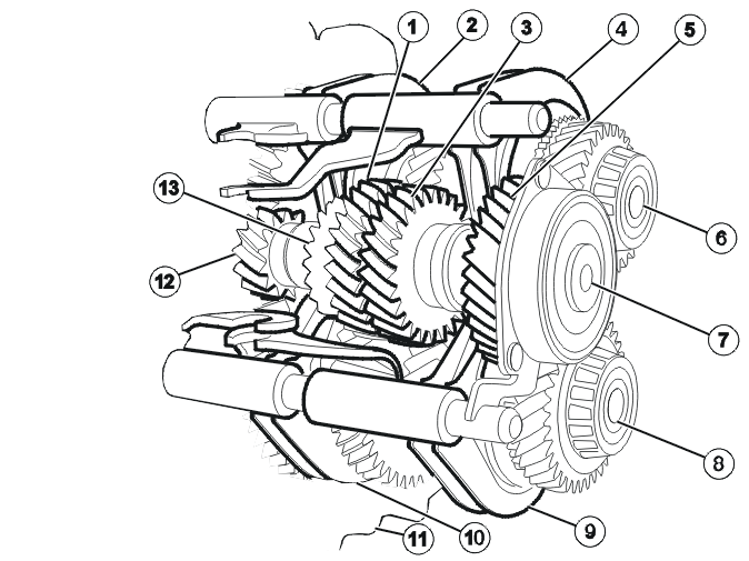
| 1 | 5th gear gear wheel | 8 | The output shaft 1st, 2nd, 3rd, and 4th gears |
| 2 | Gear selector fork for synchronizing unit for back-up gear | 9 | Gear selector fork for the synchronizing unit for 3rd and 4th gears |
| 3 | 3rd gear gear wheel | 10 | Gear selector fork for the synchronizing unit for 1st and 2nd gears |
| 4 | Gear selector fork for the synchronizing unit for 5th and 6th gears | 11 | Clutch cover |
| 5 | 4th and 6th gear gear wheel | 12 | 1st gear gear wheel |
| 6 | Output shaft for 5th and 6th gear and back-up gear | 13 | 2nd gear gear wheel |
| 7 | Input shaft |
All driven gear wheels in the transmission are on the input shaft. The input shaft is solid. The input shaft has a ball bearing and a roller bearing. This design solution does not require preloading or adjustment shims. The seal for the input shaft is pressed into the clutch cover.
Transmission input shaft
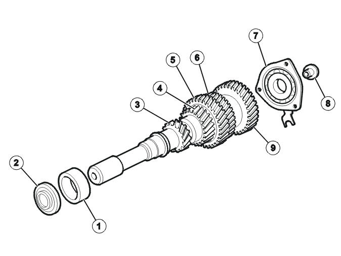
| 1 | Ball bearing, clutch housing | 6 | 3rd gear gear wheel |
| 2 | Radial oil seal | 7 | Bearing retainer |
| 3 | 1st gear gear wheel | 8 | Mounting screw, bearing |
| 4 | 2nd gear gear wheel | 9 | 4th and 6th gear gear wheel |
| 5 | 5th gear gear wheel |
The gear wheel for 1st and 2nd gears are an integrated part of the input shaft. The gear wheel for 3rd and 5th gears and the gear wheel for 4th and 6th gears are pressed on the shaft.
Due to the extreme pressure used when the gear wheels are pressed on the shaft, they cannot be pressed loose during service work. A defective input shaft can only be replaced as a complete unit.
Defective bearings can be pressed loose and replaced.
The transmission output shaft, gears 1, 2, 3 and 4
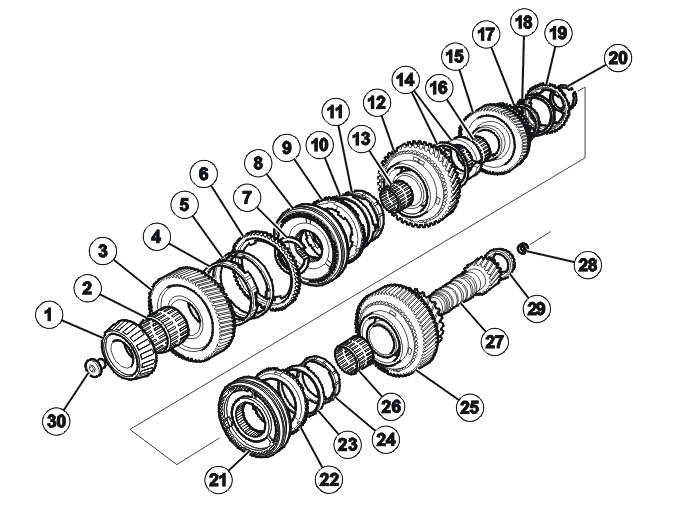
| 1 | Conical roller bearing, transmission housing | 16 | Needle bearing |
| 2 | Needle bearing | 17 | Inner synchronizing ring |
| 3 | 4th gear gear wheel | 18 | 2nd gear synchronizing cone |
| 4 | Inner synchronizing ring | 19 | Outer synchronizing ring – 2nd gear |
| 5 | 4th gear synchronizing cone | 20 | Snap ring |
| 6 | Outer synchronizing ring – 4th gear | 21 | Synchronizing unit – 1st and 2nd gears |
| 7 | Snap ring | 22 | Outer synchronizing ring – 1st gear |
| 8 | Synchronizing unit 3rd and 4th gear | 23 | 1st gear synchronizing cone |
| 9 | Outer synchronizing ring – 3rd gear | 24 | Inner synchronizing ring |
| 10 | 3rd gear synchronizing cone | 25 | Gear wheel 1st gear |
| 11 | Inner synchronizing ring | 26 | Needle bearing |
| 12 | Gear wheel 3rd gear | 27 | Output shaft, gears 1, 2, 3 and 4 |
| 13 | Needle bearing | 28 | Oil collection ring |
| 14 | Thrust washers | 29 | Conical roller bearing, clutch housing |
| 15 | Gear wheel 2nd gear | 30 | Mounting screw, bearing |
The output shaft for 1st, 2nd, 3rd, and 4th gears is hollow. The internal oil ducts lubricate the needle bearings and the roller bearings and the synchronizing units. The output shaft for 1st, 2nd, 3rd, and 4th gears runs on the conical roller bearing. This bearing assembly operates on condition that the shaft is preloaded. Shims are used to achieve this preloading.
The output final drive gear on the output shaft for 1st, 2nd, 3rd and 4th gears is an integrated part of the shaft.
CAUTION: Note the position of the oil collection ring when installing. If the oil collection ring is incorrectly positioned, the transmission fluid pressure can drop in the output shaft resulting in insufficient lubrication.
Transmission output shaft, 5th, 6th and back-up gears
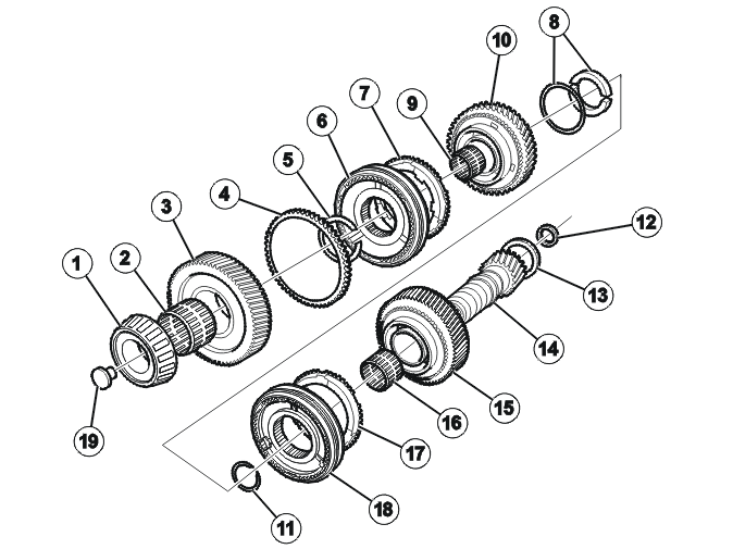
| 1 | Conical roller bearing, clutch housing | 11 | Snap ring |
| 2 | Needle bearing | 12 | Oil collection ring |
| 3 | Gear wheel 6th gear | 13 | Conical roller bearing, clutch housing |
| 4 | Synchronizing unit 6th gear | 14 | Output shaft, 5th, 6th and back-up gears |
| 5 | Snap ring | 15 | Back-up gear |
| 6 | Synchronizing unit – 5th and 6th gears | 16 | Needle bearing |
| 7 | Synchronizing ring 5th gear | 17 | Synchronizing ring back-up gear |
| 8 | Thrust washers | 18 | Synchronizing unit, back-up gear |
| 9 | Needle bearing | 19 | Mounting screw, bearing |
| 10 | Gear wheel 5th gear |
The output shaft for 5th, 6th and back-up gears is hollow. The internal oil ducts lubricate the needle bearings and the roller bearings and the synchronizing units.
The output shaft for 5th, 6th and back-up gears runs on conical roller bearings. This bearing assembly operates on condition that the shaft is preloaded. Shims are used to achieve this preloading.
The output final drive gear on the shaft for 5th and 6th and back-up gears is an integrated part of the shaft.
An oil collection ring has been installed on both output shafts.
CAUTION: Note the position of the oil collection ring when installing. If the oil collection ring is incorrectly positioned, the transmission fluid pressure can drop in the output shaft resulting in insufficient lubrication.
Gear selector, internal
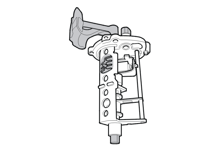
The shift unit is in the transmission housing and is secured by four screws. The shift unit consists of:
- Aluminum housing with integrated bearing and integrated seal
- Support with integrated selector guide
- Bearing, gear selector gate and end stop for the lateral movement arm.
The shift unit is consolidated in a shift control unit assembly.
Back-up gear in the gear selector assembly is furthest to the left and forward. Neutral is between 3rd and 4th.
The reversing light switch is in the shift control unit and is actuated by the shaft for lateral movement. The reversing light switch is directly connected to the Central Electronic Module (CEM).
The shift control unit must not be taken apart. In the event of a fault, the entire control unit must be replaced.
Four gear selector forks transfer the movement from the selector unit to the relevant coupling sleeve.
Gear selector assembly and mechanical transmission cables
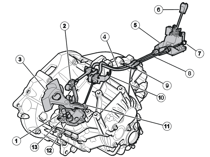
- Ventilation
- Adjustment mechanism for mechanical gear selector cables
- Gear shift lever
- Mechanical transmission cable for lateral travel
- Gear selector assembly
- Gear selector lever and gear knob
- Ball and lever for mechanical gear selector cables
- Mechanical gear shift cable
- Body lead-in (seal in the cowl, made of rubber)
- Mechanical cable bracket
- Ball and lever for mechanical gear shift cables
- Reversing light switch
- Shift unit.
The movements of the gear selector lever are transferred to the transmission via the two mechanical cables. This requires limited force for gear shifts and ensures that each gear selection is distinct. Vibration and other movement from the transmission is not felt through the gear selector lever.
The mechanical gear shift cables are color marked to reduce the risk of mixing up the cables.
- The end of the mechanical transmission cable for lateral travel is gray
- The end of the mechanical shift cable is black.
The mechanical transmission cable for lateral travel crosses the shift cable in the engine compartment.
Only the mechanical transmission cable for lateral travel can be adjusted. The mechanical transmission cable for lateral travel is adjustable lengthwise. The adjuster is positioned on the mounting towards the lever on the transmission (1). When adjusting, the spring in the gear selector assembly pulls the mechanical cable and then the mechanical cable is locked by hand using the catch. When locking, the gear selector lever must be in the neutral position and the components in the transmission must be in shift position 3 or 4.
The mechanical cables sleeves are secured in the gear selector assembly using quick-release connectors and to cable bracket on the transmission. The mechanical cables ends are secured with ball joints to the gear selector assembly and to the levers in the transmission.
In the event of a faults or damage with any of the mechanical cables, both mechanical cables must be replaced at the same time.
There is a return spring on the lateral movement lever. The shift control unit in the transmission also has a return spring.
Spring-loaded reverse inhibitor (- 2005)
The reverse inhibitor consists of a spring-loaded detent in the gear selector assembly.
Mechanical reverse inhibitor (2006 -)
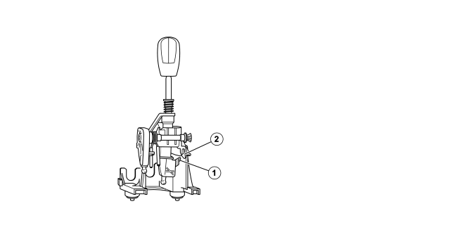
- Pin
- Stop
To prevent the accidental engagement of reverse gear, the gear selector assembly has a mechanical reverse inhibitor. The inhibitor consists of a pin (1) that sits on the gear selector lever and a stop (2) that sits on the gear selector assembly. When the gear selector lever is moved to the left, the pin is pressed against the stop. This prevents the lever from moving farther to the left than the position between 1st and 2nd gear.
To engage reverse, the lever must be pressed down so that the pin goes under the stop.
Differential
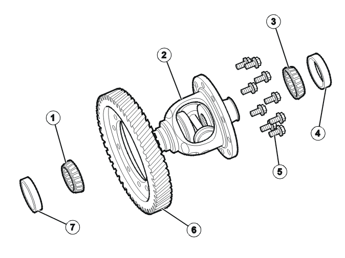
- Conical roller bearing, transmission housing
- Differential unit
- Conical roller bearing, clutch housing
- Bearing shell, conical roller bearing
- Crown wheel bolts
- Crown wheel
- Bearing shell, conical roller bearing
The differential distributes power equally between the drive wheels, even if the drive wheels are rotating at different speeds.
Synchronization
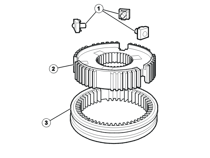
- Companion flange section
- Synchronizing hub
- Coupling sleeve.
The synchronizing units, interlock ball, springs and companion flange section make up a single unit. The synchronizing rings are made of brass. 1st, 2nd, 3rd and 4th gears have double synchronizing rings. 5th, 6th and back-up gears have a single synchronizing ring.
The synchronizing units for 1st, 2nd, 3rd and 4th gears are on the output shaft for 1st, 2nd, 3rd and 4th gears.
The synchronizing units for 5th, 6th gear and back-up gears are on the output shaft for 5th, 6th and back-up gears.
Clutch, general
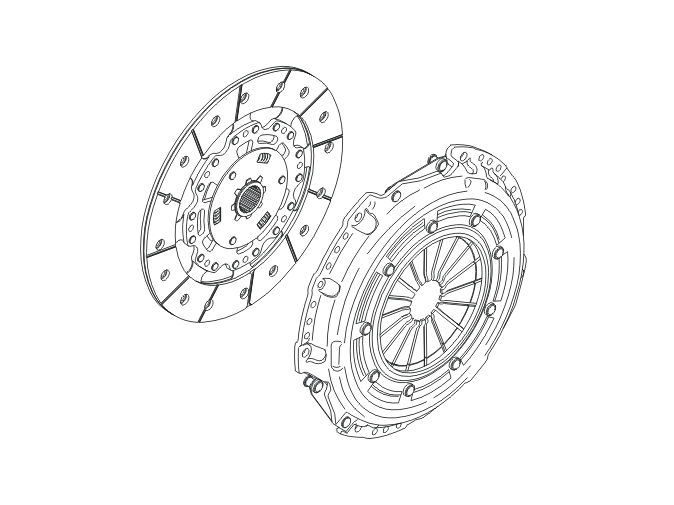
The clutch is between the engine and transmission. It consists mainly of a pressure plate and a clutch driven plate. The clutch transfers torque to and from the transmission and then on to drive the wheels.
The clutch is a single disc dry clutch. The clutch disc is connected to the transmission input shaft.
On vehicles with more powerful engines, self-adjusting clutches are used to lower the engagement forces.
MMT6 has self-adjusting clutch of the XTend type.
Hydraulic clutch control mechanism
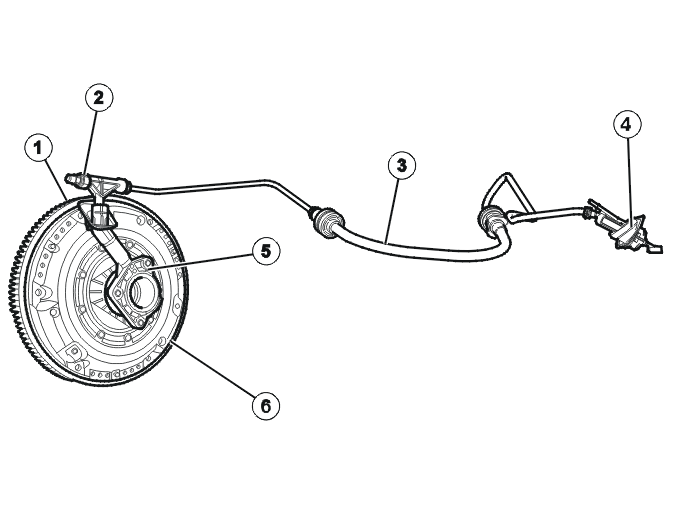
- Dual mass flywheel
- Air-bleed nipple
- Hydraulic hose
- Master cylinder
- Clutch slave cylinder
- Pressure plate (self-adjusting).
Clutch control is based on a well proven system with hydraulic power transmission.
There are ratios built-in to the system to reduce the force required to transfer torque:
- pedal ratio
- hydraulic ratio
- clutch pressure springs ratio.
The force is reduced from approximately 8600 N at the clutch to approximately 100 N at the pedal.
Shock load limiter
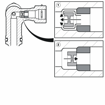
If the clutch pedal returns too quickly, the drive line could be damaged by the high torque. There is a shock load limiter in the clutch to avoid this. The shock load limiter chokes the flow between the clutch slave cylinder and the master cylinder if there is a danger of excessive torque. The shock load limiter is in the air bleed adapter on the clutch cable.
Clutch slave cylinder
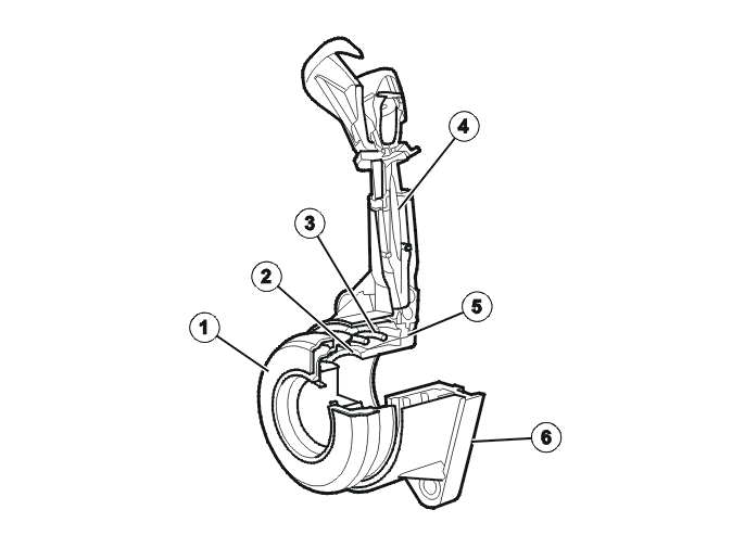
- Throwout bearing
- Protective cap
- Pressure spring
- Hydraulic duct
- Radial seal
- Plastic housing.
During unaffected conditions the clutch slave cylinder applies a pressure of 100 N on the throwout bearing on the diaphragm spring to the clutch pressure plate. This reduces wear on the throwout bearing. The throwout bearing does not need to accelerate to engine speed when the clutch is engaged.
The hydraulic clutch system is bled via the bleed valve. The bleed valve is in the hydraulic line of the feed and return lines.
The self-adjusting clutch mechanism reduces the operating range of the clutch slave cylinder, which protects the radial seal. The clutch slave cylinder therefore only requires replacement if leakage occurs and if the transmission has been removed. This is because dirt and corrosion can cause damage to the seal after the system has been removed.
To achieve a better seal on the transmission, the radial oil seal for the input shaft is not integrated in the clutch slave cylinder.
Self-adjusting clutch ( XTend)
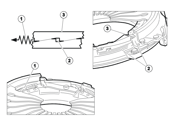
- Spring
- Adjustment ring
- Wear sensor.
A self-adjusting clutch XTend detects the wear on the clutch plate and adjusts the wear using a adjustment mechanism between the sun spring and the clutch housing. The adjustment mechanism maintains the position of the sun spring and ensures that the pedal effort required remains constant throughout the service life of the vehicle.
The advantages of the self-adjusting clutch are:
- Constant load during the entire service life of the clutch
- Increased service life for the clutch driven plate
- Reduced length of stroke for the throw out bearing.
Pressure plate
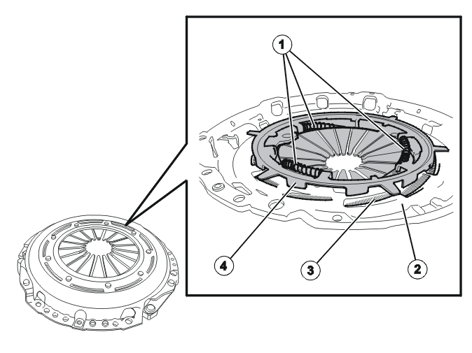
- Pressure springs
- Pressure plate (housing)
- Ramp
- Ramp ring.
The clutch is a single disc dry clutch. Pre-tensioned lifting springs connect the clutch housing and the pressure plate.
As self-adjusting clutches cannot be reset when the clutch driven plate has been replaced, the pressure plate must be replaced.
The pressure plate is the diaphragm spring type. Unlike a traditional type, the pressure plate contains an adjustment ring made of steel or plastic. If there is wear, the adjustment ring moves slightly to maintain the engagement position of the clutch.
The fact that the springs are unable to move backwards has the following advantages:
- increased wear capacity
- the clutch cover can be made shorter because space is not required for rearward movement of the diaphragm spring.
Clutch driven plate
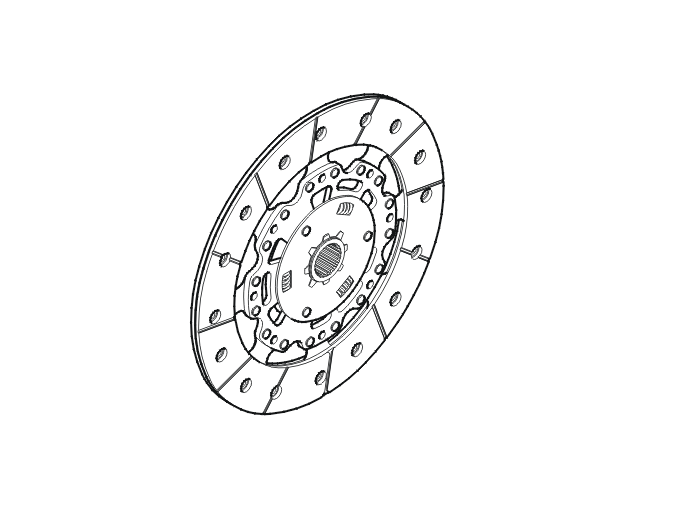
The clutch driven plate transfers engine torque to the transmission input shaft. The plate has a damper to reduce idle rattling. The inside of the plate center is lubricated when the plate is mounted at the factory. This reduces friction between the clutch driven plate and the input shaft, which makes shifting easier.
When replacing the clutch driven plate, the input shaft must be lubricated. See the instructions for replacing the clutch.
It is not possible to replace only the clutch driven plate with these types of clutch. The pressure plate and clutch driven plate must be replaced at the same time.
Dual mass flywheel
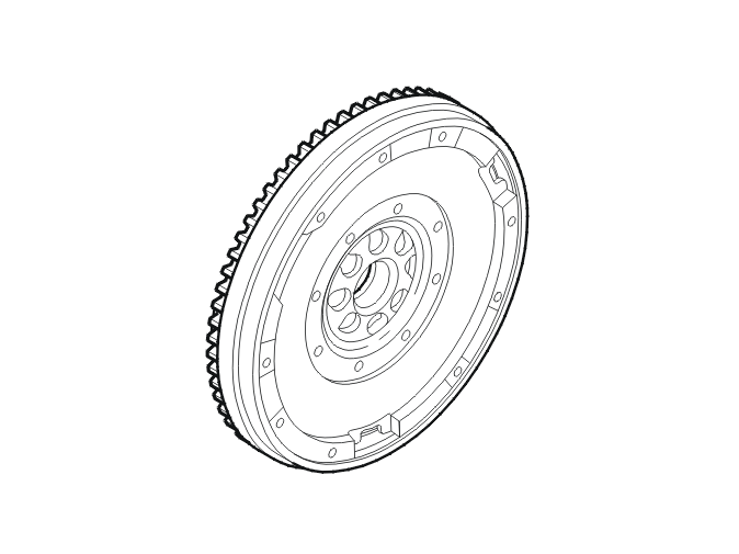
The dual mass flywheel reduces noise from the transmission and improves drivability.
The dual mass flywheel helps reduce the load on the crankshaft bearings. It also improves shift quality because the flywheel mass on the clutch driven plate is less.
The component parts of the dual mass flywheel can turn in relation to each other. The amount by which they turn depends on the engine load. On the dual mass flywheel the component parts can turn by up to 60 degrees in both directions. A certain amount of turning can be felt between the component parts if a dual mass flywheel is turned.
Clutch pedal
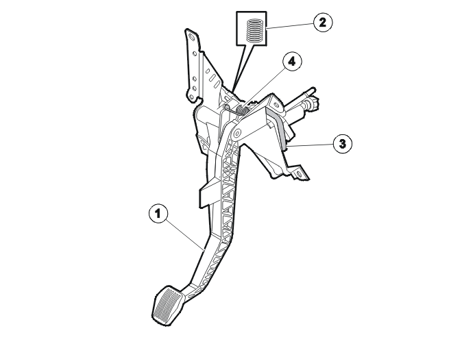
- Clutch pedal
- Clutch pedal support spring
- Body seal
- Clutch return spring.
The clutch pedal on vehicles with MMT6 transmissions, has a support spring which reduces the load force on the clutch. The support spring is angled and therefore functions as a pressure spring in a certain clutch pedal position, thus supporting the pedal force.
Parts & tools for this job For 2011 Volvo V60
- TOOLTorque wrenchSearch: 3/8 inch torque wrench
- TOOLSocket setSearch: socket set metric
- BOOKHaynes manualSearch: Haynes manual Volvo V60
Links open Amazon search results in a new tab. As an Amazon Associate I earn from qualifying purchases.