
Fuel system
- Make
- Volvo
- Model
- XC70 V70 XC / XC70 Factory Service Manual
- Year
- 2001–2007
- Section
- 09 Miscellaneous › Design and Function › Fuel system
Fuel system
Combustion process
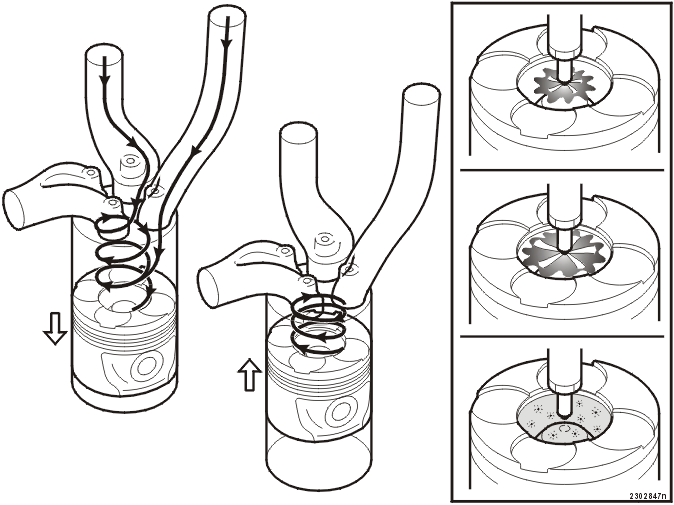
General
- The cylinder head has two separate inlet ducts with different geometry for each cylinder. The front duct is a tangential duct and the rear is a spiral duct
- During the inlet phase there is considerable swirl development around the inlet valve in the spiral duct. In combination with the air flow from the tangential duct this creates significant swirl around the center of the cylinder
- During the compression phase, the swirl development is increased further by the shape of the piston and is concentrated around its combustion chamber. This results in an even distribution of air throughout the combustion chamber, which is a prerequisite for optimal combustion
- Fuel is sprayed into the cylinder at high pressure. The timing of the injection depends on load and engine speed.
The three combustion phases:
Premixed combustion
- Some fuel is injected in and forms a homogenous fuel/air mixture before it ignites. The pressure and temperature increase rapidly when the mixture ignites.
Diffusion combustion
- Combustion continues while fuel is sprayed in and mixes with the air.
Late combustion
- The combustion continues into the expansion phase (after the injection has ceased). This happens when there are hydro-carbons bound in the carbon particles and other fuel rich contaminants which oxidize slowly.
Fuel distribution
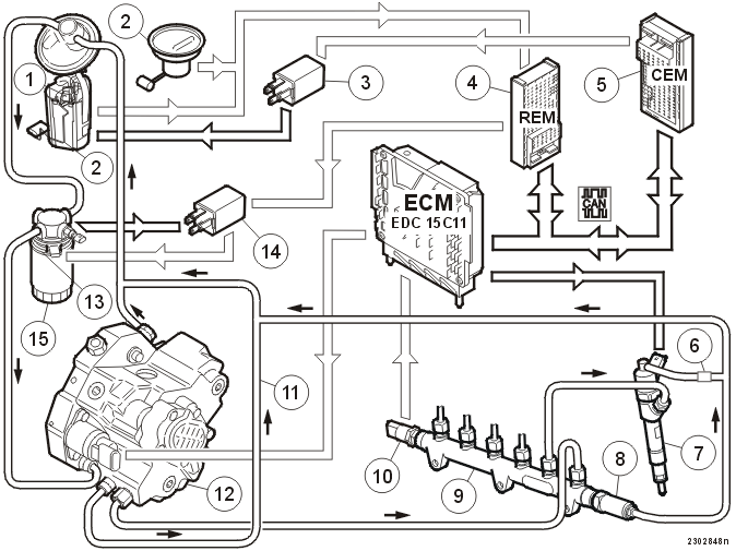
| 1 | Electrical fuel pump (FP) | 9 | Fuel rail |
| 2 | Fuel level sensor | 10 | Fuel pressure sensor |
| 3 | Fuel pump relay | 11 | Return line |
| 4 | Rear Electronic Module | 12 | Low and high pressure pumps |
| 5 | Central Electronic Module | 13 | Heater element |
| 6 | Check valve | 14 | Heater element relay |
| 7 | Injectors | 15 | Fuel filter with temperature sensor |
| 8 | Relief valve |
Electrical fuel pump (FP)
Supplies fuel to the low-pressure pump:
- 80 seconds each time the ignition key is turned to position II. When the key is turned to position III the pump runs until the engine is started
- under high loads.
The engine control module (ECM) sends a request to the central electronic module to start the pump.
Fuel is transferred using the ejector principle from the left-hand fuel pocket to the right-hand pocket depending on the amount of fuel in the right-hand gallery.
- The fuel level sensor in the right-hand fuel gallery transmits data to the rear electrical module about the amount of fuel. The rear electrical module transmits a CAN signal on the network which is retrieved by the central electronic module
- The central electronic module activates the fuel pump (FP) relay when the level in the right-hand gallery falls below 13 liters and deactivates the relay at 21 liters. If the signal for the amount of fuel is missing, the central electronic module activates the fuel pump (FP) to guarantee the fuel level
- There are two valves integrated in the fuel pump (FP). There is a check valve, whose task is to prevent the low-pressure fuel pump (FP) from drawing fuel through the electrical fuel pump (FP). There is also a pressure limiting valve in the fuel pump (FP) which limits the pressure to approximately 300 kPa absolute pressure in the supply line to the filter
- The operating pressure of the fuel pump (FP) is approximately 200 kPa absolute pressure.
Fuel filter
The fuel filter has a heater element and a temperature sensor which detects the fuel temperature.
A relay, controlled by the temperature sensor and the rear electrical module (which receives an "engine running" signal from the engine control module (ECM) via the central electronic module) supplies the heater element with power.
Warming up begins at temperatures below -3° C and shuts off at +5° C.
Low and high pressure pumps
The low-pressure fuel pump (FP) retrieves fuel from the tank and supplies the rest of the pump with fuel.
The high-pressure fuel pump (FP) supplies the fuel rail with fuel at variable pressure.
Fuel rail
Supplies fuel to the injectors at high pressure, between approximately 30-160 MPa.
Fuel pressure sensor
Transmits data about the fuel pressure in the fuel rail to the engine control module (ECM).
Relief valve
The relief valve opens if the pressure in the fuel rail exceeds 190 MPa.
Injectors
Open sequentially and are controlled by the engine control module (ECM).
Check valve
In order to maintain a certain pressure in the return line from the injectors, there is a check valve on the common return line to the fuel tank.
Low and high pressure pumps
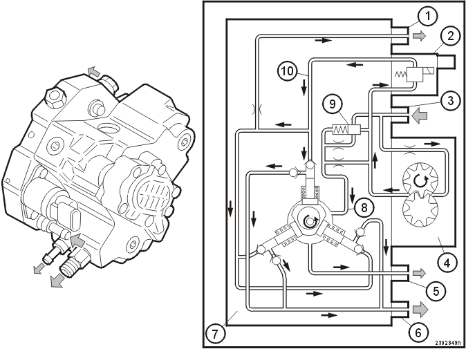
| 1 | Return, bleed circuit | 6 | Outlet to the fuel rail |
| 2 | Fuel pressure control valve | 7 | High pressure pump |
| 3 | Inlet from the tank | 8 | Cooling and lubrication duct |
| 4 | Low-pressure fuel pump | 9 | By-pass valve |
| 5 | Return, cooling and lubrication circuit | 10 | Inlet duct, high-pressure fuel pump |
The pump unit is driven directly by the camshaft for the intake valves. In the pump unit are:
- low-pressure fuel pump
- high-pressure fuel pump
- a fuel pressure control valve which regulates the quantity of fuel to the high-pressure fuel pump
- a by-pass valve which leads excess fuel back to the low-pressure fuel pump.
The lower pressure fuel pump is gear type and is driven by the pump shaft.
The high pressure pump consists of three plungers against a cam. The forward and return movement of the pump is achieved by the cam driving an eccentrically positioned carrier. A return spring ensures that the plungers are always in contact with the cam.
The fuel pressure control valve is electro-hydraulic and is controlled by the engine control module (ECM).
The by-pass valve is a mechanical/hydraulic valve.
Function
The low-pressure fuel pump (FP) draws fuel from the tank.
The fuel is then pressurized by the low-pressure fuel pump.
Unchoked, the fuel is led to:
- the inlet for the fuel pressure control valve
- the plunger for the by-pass valve.
Choked, the fuel is led to:
- the lubrication and cooling duct
- the reverse of the plunger for the by-pass valve
- through an additional choke valve on the side of the plunger for the by-pass valve. This pressure acts as a balancing pressure.
Fuel pressure control valve
The fuel pressure control valve controls the amount of fuel to the high pressure pump.
The pressure in the fuel rail depends on the amount of fuel that is supplied to the plungers in the high pressure pump. The engine control module (ECM) calculates the desired pressure and uses a pulse width modulation (PWM) signal to control the flow through the fuel pressure control valve.
The pressure in the fuel rail varies from approximately 30 MPa at idle to approximately 160 MPa under full load and an engine speed above 2700 rpm.
By-pass valve
When there is only low demand for fuel from the high pressure fuel pump but the engine speed is high (during downhill engine braking for example), the excess fuel supplied by the low pressure fuel pump is evacuated. To do this the by-pass valve opens. The excess fuel is led back to the inlet on the low pressure fuel pump.
Other
The pump has an automatic bleeding system. The inlet channel for the high pressure fuel pump has an inner choked duct in the pump unit which leads the return fuel to the tank. This evacuates any air that may remain in the fuel. The outlet is at the top of the pump unit. This guarantees that all remaining air returns with the fuel to the tank.
The fuel is led from the lubrication and cooling circuit via a duct to the common return line for the tank.
Injectors
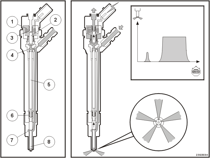
| 1 | Coil | 5 | Push rod |
| 2 | Valve | 6 | Spring, lower chamber |
| 3 | Spring, upper chamber | 7 | Lower chamber |
| 4 | Upper chamber | 8 | Fuel needle |
Function
The fuel is supplied at high pressure and pressurizes both the upper and lower chambers.
When the valve in the upper chamber is closed, the pressure in the chambers is the same.
Activation
The injectors are controlled sequentially by the engine control module (ECM) which contains a driver stage.
To ensure that the fuel needle in the injector is lifted quickly, the coil is supplied with a voltage of approximately 80V and a current during the opening phase of approximately 20A.
The valve opens when the coil is activated. The fuel in the upper chamber is returned via the return line and the pressure in the upper chamber falls. This causes the higher pressure in the lower chamber to act on the fuel needle which is raised and fuel is injected.
The current drops to approximately 12A during the open phase.
Closing
When the current supply to the coil ceases, the valve in the upper chamber is closed by the spring.
The fuel needle is closed when the pressure in the upper and lower chambers has equalized.
The check valve on the return line for the injectors acts as a vibration damper for the moving components in the upper chamber of the injector.
Priming and main injection
At low engine speeds and under low loads, the injectors can be activated to give priming of approximately 1-3 % of the calculated quantity of fuel. The main injection then takes place with the remaining quantity of fuel.
Priming occurs at idle speed and at low loads up to approximately 3400 rpm.
The advantage of priming is that a small amount of fuel is ignited. This prevents a sudden increase in the cylinder pressure, resulting in a lower noise level.
The amount of fuel is calculated using a number of factors. These include the position of the accelerator pedal (AP), the engine coolant temperature (ECT), the engine speed, height above sea level (i.e. air pressure) and smoke limitation based on calculations made by the engine control module (ECM).
Glow plugs
The glow plugs are activated in two phases. Preheating and post-heating.
Preheating
- Occurs when the ignition key is in position II. Time and coolant temperature dependent. Indicated in the driver information module
- Occurs during the time that the starter motor is activated. Time dependent. No indication in the driver information module
- Occurs during the time that the starter motor is activated. Time dependent. No indication in the driver information module.
Post-heating
Takes place after the engine has started. Time, coolant temperature and engine speed dependent. No indication in the driver information module.
Example
Engine coolant temperature (ECT) -6° C. After start, the engine runs at idle for 60 seconds. The car departs and exceeds a predetermined engine speed (RPM). The heating (glow) time will be:
Phase | Time in seconds |
| Preheating period | 6 seconds |
| Starter motor activated | 2 seconds |
| Idling speed | 60 seconds |
| Total | 68 seconds |
If the engine speed (RPM) falls below the parameter, the preheating resumes until a certain time factor is exceeded.
The relay which activates the preheating is controlled by the engine control module (ECM).
Emission cleaning
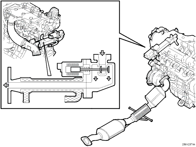
Catalytic converters
D5244T/D5244T2 engines have two catalytic converters:
- A front catalytic converter positioned immediately after the turbocharger (TC). This means that the catalytic converter rapidly reaches the correct temperature after start
- A rear catalytic converter is positioned under the floor. By using this catalytic converter and the increasing the active surface, the capacity to reduce harmful emissions is increased.
Because the catalytic converters are positioned close to each other, the rear catalytic converter also reaches operating temperature rapidly.
The catalytic converters are oxidation catalytic converters. Because a diesel engine always runs with excess air, the hydro-carbons and carbon monoxide are reduced through oxidation.
Because the hydro-carbon contaminants in the carbon particles are oxidized when they pass the catalytic converter, both the mass of the particles and the amount of particles emitted is reduced.
The catalytic converters have a ceramic carrier covered in aluminum oxide which has the effect of increasing the surface area. The aluminum oxide is in turn impregnated with a thin layer of noble metal which functions as active material for the catalytic process.
EGR (Exhaust Gas Recirculation)
In order to reduce the release of nitrous oxides (NOx), the engines have an exhaust gas recirculation system. To reduce the temperature of the returned exhaust gases, they pass through a cooler placed before the intake manifold.
Coolant encloses the pipes through which the exhaust gases passes. Under certain situations, the temperature of the exhaust gases is reduced by up to approximately 180° C. This lower temperature further reduces NOx.
When exhaust gases are not flammable and they are at a lower temperature than the combustion process and contain a lot of condensation, the combustion temperature drops and the release of NOx is reduced.
The amount of recirculated exhaust gases is controlled by the engine control module (ECM) which uses a signal to control the solenoid for the exhaust gas recirculation (EGR) valve.
The quantity of recirculated exhaust gases depends on factors such as the engine coolant temperature (ECT), engine speed (RPM) and load.
Parts & tools for this job For 2001 Volvo XC70
- PARTFuel filterSearch: Volvo XC70 2001 fuel filter
- TOOLFuel pressure test kitSearch: fuel pressure test kit
- TOOLFuel line disconnect toolSearch: fuel line disconnect tool
Links open Amazon search results in a new tab. As an Amazon Associate I earn from qualifying purchases.