audi Workshop Repair Guides

Audi Workshop Service and Repair Manuals

Checking camshaft axial clearance > < Checking compressions
4-Cylinder engine (5-valve), Mechanics
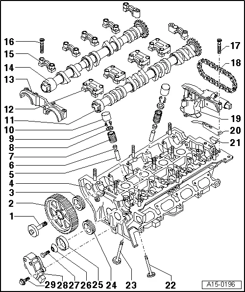
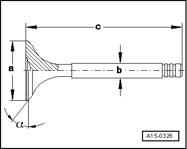
Servicing valve gear

Notes:

  • ◆ Cylinder heads which have cracks between the valve seats or between valve seat inserts and the spark plug thread can be used further without reducing service life, provided the cracks do not exceed a maximum of 0.3 mm in width, or when no more than the first 4 turns of the spark plug threads are cracked.
  • ◆ After installing the camshaft, wait for about 30 minutes before starting the engine. The hydraulic tappets must be allowed to settle, otherwise the valves will contact the pistons.
  • ◆ After working on the valve gear, turn the engine carefully at least 2 rotations to ensure that none of the valves make contact when the starter is operated.
  • ◆ Renew seals and gaskets.
 
A15-0196
  • 65 Nm
    • ◆ Use counter-hold 3036 to loosen and tighten =>Fig.13-22
  • Camshaft sprocket
    • ◆ For exhaust camshaft
    • ◆ Note installation position:
      narrow rim flange facing forward and TDC marking for cylinder 1 visible from the front
  • Oil seal
    • ◆ For exhaust camshaft
    • ◆ Renewing
  • Cylinder head
    • ◆ See note
      => Page 15-38
    • ◆ Checking valve guides
      => Page 15-80
    • ◆ Reworking valve seats
      => Page 15-82
    • ◆ Dowel sleeves for bearing caps must be located in cylinder head
 
A15-0196
  • Valve guide
    • ◆ Checking => Page 15-80
  • Valve stem seal
    • ◆ Renewing=> Page 15-72
  • Valve springs
    • ◆ Removing and installing
      => Page 15-72
  • Valve spring plate
  • Valve cotters
  • Hydraulic bucket tappet
    • ◆ Checking => Page 15-69
    • ◆ Removing and installing
      => Page 15-72
    • ◆ Do not interchange
    • ◆ Store with cam lobe contact surface downwards
    • ◆ Before installing check camshaft axial clearance => Page 15-46
    • ◆ Oil contact surface
 
A15-0196
  • Inlet camshaft
    • ◆ Check radial clearance with
      Plastigage (bucket tappets not installed)
      Wear limit: 0.1 mm
    • ◆ Run-out: max. 0.035 mm
    • ◆ Checking axial clearance
      => Page 15-46
    • ◆ Removing and installing camshafts
      => Page 15-58
  • Bearing cap for inlet camshaft
    • ◆ Must be located on dowel sleeves
    • ◆ Dowel sleeves must be located in cylinder head
    • ◆ Note installation position
    • ◆ Installation sequence
      => Page15-62
  • Double bearing cap
    • ◆ Must be located on dowel sleeves
    • ◆ Dowel sleeves must be located in cylinder head
    • ◆ Apply a small amount of sealant to sealing surface before installation
      => Page 15-66
    • ◆ Liquid sealant

=> Parts List

 
A15-0196
  • Exhaust camshaft
    • ◆ Check radial clearance with Plastigage (bucket tappets not installed)
      Wear limit: 0.1 mm
    • ◆ Run-out: max. 0.035 mm
    • ◆ Checking axial clearance
      => Page 15-46
    • ◆ Removing and installing camshafts
      => Page 15-58
  • Bearing cap for exhaust camshaft
    • ◆ Must be located on dowel sleeves
    • ◆ Dowel sleeves must be located in cylinder head
    • ◆ Note installation position
    • ◆ Installation sequence
      => Page15-62
  • 10 Nm
  • 10 Nm
  • Drive chain
    • ◆ Check for wear
    • ◆ Mark position of chain before removing=> Page 15-61
    • ◆ Removing and installing:
      => "Removing and installing
      camshaft," Page 15-58
 
A15-0196
  • Camshaft adjuster
    • ◆ With solenoid valve for camshaft adjustment -N205
    • ◆ Checking
    • ◆ Hold in position with retainer for chain tensioner 3366 before removing
    • ◆ Removing and installing
      => Page 15-58
  • Metal/rubber gasket
    • ◆ Coat with sealant before installing
      => Page 15-62
    • ◆ Liquid sealant

=> Parts List

  • Gasket
    • ◆ Renew
  • Exhaust valve
    • ◆ With sodium filling
    • ◆ Note instructions on scrapping valves with a sodium filling => Page 15-45
    • ◆ Do not rework, only grinding-in is permitted
    • ◆ Valve dimensions
      => Fig. 15-45
    • ◆ Checking valve guides
      => Page 15-80
    • ◆ Reworking valve seats
      => Page 15-82
 
A15-0196
  • Inlet valve
    • ◆ Do not rework, only grinding-in is permitted
    • ◆ Valve dimensions
      => Fig. 15-45
    • ◆ Checking valve guides
      => Page 15-80
    • ◆ Reworking valve seats
      => Page 15-82
  • Oil seal
    • ◆ For inlet camshaft
    • ◆ Renewing=> Page 15-53
  • Hall sender rotor
    • ◆ Note installation position:
      locate lug in notch on camshaft
  • Washer
    • ◆ Conical
    • ◆ Note installation position
  • 25 Nm
  • Housing for Hall sender -G40
  • 10 Nm
 
A15-0326

→ Fig. 1    Valve dimensions

Note:

Inlet and exhaust valves must not be reworked. Only grinding-in is permitted.

Dimension

Inlet valve

Exhaust valve

dia. a

mm

26.80 ... 27.00

29.80 ... 30.00

dia. b

mm

5.95 ... 5.97

5.94 ... 5.95

c

mm

104.84 ... 105.34

103.64 ... 104.14

α

45

45

Caution
  • ◆ Worn exhaust valves with sodium filling must not be disposed of until they have been treated as follows:
  • ◆ The valves must be sawn into two sections with a metal saw at a point between the centre of the shaft and the valve head. They must not come into contact with water when this is done. Then throw the valves into a bucket of water (not more than ten at time). Then step back because a chemical reaction occurs when the sodium filling burns.
  • ◆ After this treatment the valves can be disposed of in the normal way.

Checking camshaft axial clearance > < Checking compressions