|
Injectors, Remove and Install
 Remove Remove
|
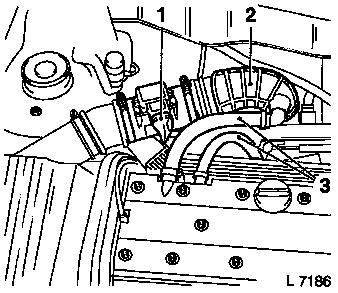
Disconnect wiring harness plug (1) from hot film mass air
flowmeter.
For Z 20 LET engine: Remove air intake pipe – see
illustration "Air Duct (Z 20 LET)".
For X 20 XEV and X 20 XER engine: Detach engine vent hoses (3)
from cylinder head cover and air intake hose (2) from throttle body
and air filter housing upper part.
Reduce fuel pressure with Pressure Tester KM-J-34730-91 via
testing port – collect escaping fuel in suitable container
– observe safety regulations and national legislation.
|
|
|
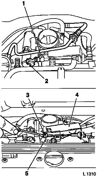
For X 20 XEV and X 20 XER engine: Remove fuel return line (1)
from fuel pressure regulator and Bowden cable bracket. Disconnect
wiring harness plug (2) from idle air control.
For Z 20 LET engine: Remove fuel feed line from fuel distributor
pipe and fuel return line from fuel pressure regulator.
For X 20 XEV and X 20 XER engine: Lift accelerator Bowden cable
retainer (3) using screwdriver and remove accelerator Bowden cable
ball socket (5) from ball.
For version with electronic cruise control: remove shackle for
cruise control Bowden cable from ball head – see operation
"Cruise Control – Bowden Cable, Remove and Install".
Detach Bowden cable retainers (4) from throttle body and lay
aside with Bowden cables towards rear.
|
|
Disconnect wiring harness plug from tank vent valve and
crankshaft pulse pick-up.
Detach spark plug cover and disconnect wiring harness plug from
camshaft sensor.
|
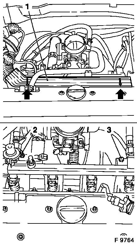
Detach plug strip (1) from injectors and place to one side.
Remove fastening pin (2) and fastening bolt (3).
Remove fuel distributor pipe with injectors from intake
manifold.
|
|
|
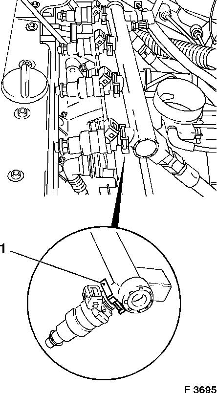
Remove each injector from fuel distributor pipe – remove
spring clip (1).
 Install
Insert injector in fuel distributor pipe with new seal rings
– secure with spring clip (1).
Caution
The positions of the spring clips for the injectors only allow
the plug strip to engage in a certain position. Align all spring
clips so that correct contact of the plug strip to the injectors is
ensured.
Install
Insert fuel distributor pipe with injectors into intake manifold
and secure using fastening pins and fastening bolt –
tightening torque 8 Nm / 6 lbf. ft.
|
|
Connect plug strip to injectors – plug strip must engage
audibly – ensure correct seating.
Connect or join wiring harness plug to crankshaft pulse pickup,
tank vent valve and camshaft sensor.
Remove ignition cable cover – tightening torque 3 Nm / 2
lbf. ft.
For X 20 XEV and X 20 XER engine: Attach Bowden cable bracket to
throttle body.
For version with electronic cruise control: attach shackle for
cruise control Bowden cable to ball head – see operation
"Cruise Control – Bowden Cable, Remove and Install".
For X 20 XEV and X 20 XER engine: Attach accelerator Bowden
cable ball socket to ball – ensure that retainer engages.
Connect wiring harness plug to intake air control.
For Z 20 LET engine: Attach fuel feed line to fuel distributor
pipe – tightening torque 15 Nm / 11.1 lbf. ft.
For X 20 XEV and X 20 XER engine: Attach fuel return line to
fuel pressure regulator – tightening torque 15 Nm / 11.1 lbf.
ft. Attach fuel return line to bracket for Bowden cables –
tightening torque 9 Nm / 6.6 lbf. ft. Attach air intake hose to
throttle body and air cleaner housing upper part – tightening
torque 3.5 Nm / 2.6 lbf. ft... Attach engine vent hoses to cylinder
head cover.
For Z 20 LET engine: Install air intake pipe – see
illustration "Air Duct (Z 20 LET)".
Connect wiring harness plug to hot film mass air flowmeter.
|
