
Functional description
- Make
- Alfa Romeo
- Model
- 145/146 Electrical System Diagnosis Manual, Volume 3
- Year
- 1994–2001
- Section
- Airbag › Functional description
FUNCTIONAL DESCRIPTION
The control unit R22 receives the "key-operated" supply, (circuit protected by fuse F15 in fusebox G1) at pin 9 - BECKER or at pin 15 - TRW.
For box "C" the supply of control unit R22 is protected by a further fuse G395 next to the box itself G1 "C".
The system comprises two cushions, one in front of the driver R23 (at the centre of the steering wheel) and one in the dashboard in front of the passenger R27.
NOTE: The cushion on the steering wheel is connected electrically through a clock spring and connector G383.
While the car travels, the control unit R22 continuously diagnoses the system, thereby checking the continuity of the circuits and of the components.
In the event of a crash, detected by the two internal sensors (one piezoelectric and one mechanical) commands activation of the two modules sending current through two signals: one earth and one 12V supply (from pins 6 and 2 - BECKER and 3 and 4 - TRW for the passenger's module and from pins 5 and 2 -
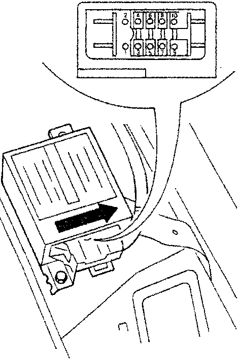
BECKER or 1 and 2 - TRW for the module on the steering wheel).
If sensor R30 (only present until June '99) signals (pins 15 and 37 of R22) that there is no passenger on the seat, the Air Bag is not activated.
When a fault or system malfunction is detected, the type of fault is logged and the warning light on the instrument panel C10 is turned on to alert the driver of the presence of a fault in the system.
From M.Y. '99, the telltale light in question is the so-called "intelligent" type: it turns on not only if the system detects an anomaly, but also in cases of lack of contact or short circuit to earth of the circuit that connects the telltale light to the relative control unit thanks to a special internal pilot circuit which checks proper connection.
Lastly connector T3 allows connection to the ALFA TESTER.
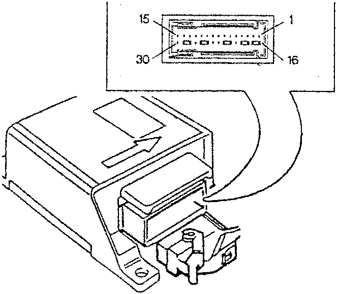
TRW CONTROL UNIT PIN-OUT
- Driver's Air Bag (-)
- Driver's side Air Bag (+)
- Passenger's side Air Bag (-)
- Passenger's side Air Bag (+)
- N.C.
- N.C.
- N.C.
- Earth for diagnosis
- Line K for diagnosis
- N.C.
- N.C.
- N.C.
- Warning light (failure and diagnosis)
- Control unit earth
- "Key-operated" supply
- Passenger presence sensor
- Passenger presence sensor
BECKER CONTROL UNIT PIN-OUT
- N.C.
- Module activation circuit (+)
- Warning light signal (and diagnosis connector)
- Diagnosis connector signal
- Passenger module activation (-)
- Steering wheel module activation (-)
- N.C.
- Earth
- "Key-operated" supply
- N.C.
Parts & tools for this job For 1994 Alfa Romeo 145/146
- TOOLOBD2 scanner with SRSSearch: OBD2 scanner ABS SRS
- TOOLTrim removal tool kitSearch: trim removal tool kit
Links open Amazon search results in a new tab. As an Amazon Associate I earn from qualifying purchases.