
Heating/ventilation fan control Q4
- Make
- Alfa Romeo
- Model
- 145/146 Electrical System Diagnosis Manual, Volume 3
- Year
- 1994–2001
- Section
- Heater › Heating/ventilation fan control Q4
145 electrical system diagnosisHeating/ventilation fan control Q4
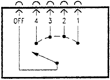
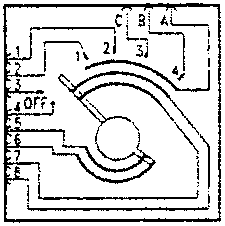
Heating/ventilation fan control Q4
Check the contacts corresponding to the different positions of the knob.
Heating/ventilation fan speed adjustment resistance Q5
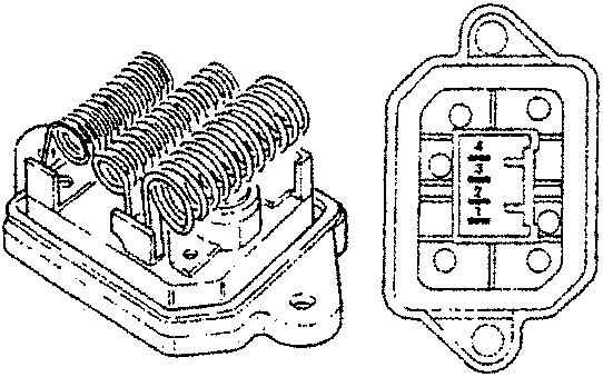
| Piece crossed | Total resistance | Fan speed |
|---|---|---|
| 4-1 | 3.55 Ω | 1st |
| 3-1 | 1.35 Ω | 2nd |
| 2-1 | 0.35 Ω | 3rd |
| none | - | 4th |
| Thermal fuse cut in temperature | 98°C | |
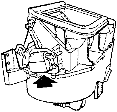
Recirculation flap control motor Q27
(only for certain versions)
| SPECIFICATIONS |
|---|
| 12 V at pin 1 and 0 V at pin 2 = counterclockwise rotation of output shaft |
| 12 V at pin 3 and 0 V at pin 2 = clockwise rotation of output shaft |
Parts & tools for this job For 1994 Alfa Romeo 145/146
- TOOLA/C manifold gauge setSearch: AC manifold gauge set
- TOOLUV leak detection kitSearch: AC UV leak detection kit
- PARTCabin filterSearch: Alfa Romeo 145/146 1994 cabin filter
Links open Amazon search results in a new tab. As an Amazon Associate I earn from qualifying purchases.