
Structure
- Make
- Alfa Romeo
- Model
- 145/146 Engines, 146 Bodywork and Engine Overhaul Manual
- Year
- 1994–2001
- Section
- Fuel supply system › Structure
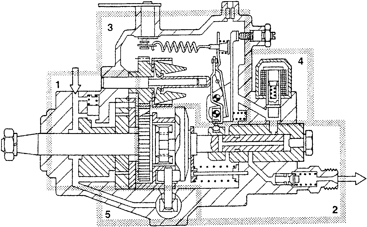
- Blade type fuel pump
This pump sucks in the diesel and sends it to the pump internal chamber. - High pressure pump with distributor
This pump generates the injection pressure, pumps and distributes the diesel. - R.p.m. mechanical adjuster
This device adjusts the r.p.m. and corrects the flow ensuring it remains within the established limits. - Stop device
Interrupts the diesel supply - Injection advance variator
Depending on the r.p.m. this device varies the start time of the delivery.
STRUCTURE
The distributor pump control shaft is supported in the pump casing and the blade type fuel pump is fitted on it.
The roller holder ring is located behind the fuel pump, which is also located in the pump casing, even though it is not integral with the control shaft.
The cam disk, which rests on the roller holder ring and is activated by the control shaft, generates a rotation-lift type movement which is transmitted to the piston distributor.
The piston distributor is guided in the distributor head, which is screwed to the pump casing. The electric stop device which interrupts the fuel supply, the threaded cap with the bleed screw and the connectors for the delivery valves are fixed in the distributor head.
The mechanical stop device, on the other hand, is located in the regulating device cover.
The adjusting lever group is made up of control, starting and tension levers and its fulcrum is housed in the distributor pump. The adjusting lever group varies the position of the adjusting cursor on the pump piston.
The adjusting spring, hooked to the shaft of the control and tension levers, is located in the upper part of the casing.
The control lever, which affects the functioning of the pump, is located through the shaft in the regulating device cover.
The regulating device cover, which also acts as a cover for the upper part of the pump, also houses the adjusting screws for the full load flow, the flow throtller and the r.p.m. adjusting screw.
The hydraulic injection advance variator is fitted transversally to the longitudinal axis under the lower part of the distributor pump.
The functioning of the variator is influenced by the pressure in the internal chamber, which, in turn, is determined by the fuel pump and by the pressure regulating valve. The variator is fixed with two covers on the sides of the pump.
Parts & tools for this job For 1994 Alfa Romeo 145/146
- PARTEngine gasket setSearch: Alfa Romeo 145/146 1994 engine gasket set
- TOOLTorque wrenchSearch: 3/8 inch torque wrench
- TOOLFeeler gauge setSearch: feeler gauge set
Links open Amazon search results in a new tab. As an Amazon Associate I earn from qualifying purchases.