
System
- Make
- Alfa Romeo
- Model
- 145/146 Factory Service Manual
- Year
- 1994–1999
- Section
- Heating and ventilation - Turbodiesel engine › System
SYSTEM
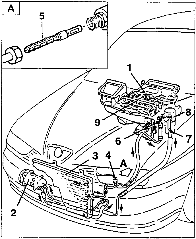
- Heating and ventilation unit
- Compressor
- Condenser
- Three-level pressure switch (trinary)
- Expansion valve
- Needle valve for charging/draining R134a on the low pressure pipe
- Needle valve for charging/draining R134a on the low pressure pipe
- Drier filter
- Evaporator
DESCRIPTION
The heating and ventilation system is of the manual type with air conditioner.
The system can be represented by three sections:
- a unit comprising the air ducting system and the heater - distributor unit.
- a closed circuit that generates cold (air conditioner).
- a control unit for certain functions of the system.
DUCTING SYSTEM AND HEATER - DISTRIBUTOR UNIT
Two types have been adopted, one described and illustrated in the various procedures with the words "two bowden" and in the other "three bowden". The variations in relation to the proceding type are given in a specific paragraph.
The assembly comprising the ducting system (A) and the heater- distributor unit (B) is shown in diagram form in cross-section in the figure below.
The ducting system (A) can in turn be divided into two parts, a lower and an upper section; one end of the latter is suitably shaped to be connected with the opening in the services box.
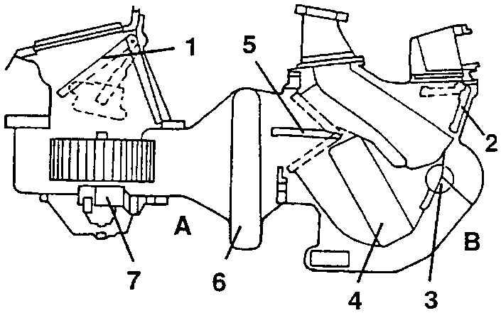
- Outside air/recirculation vent
- Upper distribution vent
- Lower distribution vent
- Heater radiator
- Mixing vent
- Evaporator
- Fan
In the upper front section, in line with the outside air inlet, there is a second opening that communicates with the passenger compartment (air inlet for the recirculation function).
Between the two air inlet openings, inside the ducting system, there is a motorised flap which is duly directed to shut off one of the two openings. The flap is controlled through a leverage by an electric actuator (motor) fastened on the outside of the system.
Inside, opposite the air inlets there is the evaporator which represents the cooler.
The fan is fitted in the lower section in correspondence of the air inlets and it operates at different speeds.
Two bowdens are connected on the lefthand side of the heating- distributor unit which are operated by the controls and suitably direct the lower, upper and air mixing and distribution flaps and they also control the position of the tap fitted on the heater radiator inlet.
AIR CONDITIONING CIRCUIT
The circuit shown in diagram form in the figure below mainly comprises the following parts:
- a compressor fitted on the engine, which draws in the cooling liquid from the evaporator;
- a condenser, fitted in front of the engine cooling radiator (high pressure circuit);
- an evaporator in the ducting system;
- a drier filter.
Parts & tools for this job For 1994 Alfa Romeo 145/146
- PARTEngine gasket setSearch: Alfa Romeo 145/146 1994 engine gasket set
- TOOLTorque wrenchSearch: 3/8 inch torque wrench
- TOOLFeeler gauge setSearch: feeler gauge set
Links open Amazon search results in a new tab. As an Amazon Associate I earn from qualifying purchases.