
Description
- Make
- Alfa Romeo
- Model
- GTV / Spider GTV and Spider (916) Factory Service Manual
- Year
- 1995–2000
- Section
- 55-1 Introduction › Description
DESCRIPTION
The first part (general description) describes the purpose of the circuit or system under examination and shows how it works: this is a condition which is necessary for each subsequent operation check and for any trouble-shooting found to be necessary.
The second part (functional description) shows the wiring diagram analytically, following the "flow" of the supply signals towards earth from the upper section downwards.
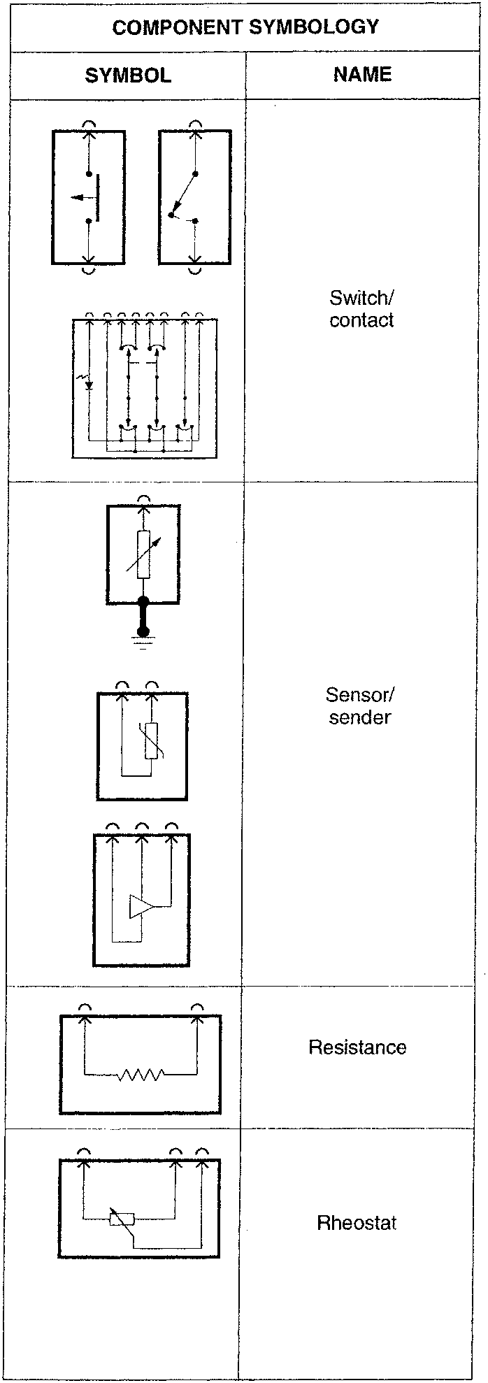
The components are identified by the same alphanumeric codes used in the diagrams (and in the key at the end of this publication).
A brief description is also given of the components which need to be outlined from an electrical point of view (eg. relays, contacts, fuses, connectors,...) in order to be able to check their functioning during the subsequent fault diagnosis tests.
LOCATION OF COMPONENTS
Schematic diagrams representing the silhouette of the car makes it easy to find the various components of the circuit under examination and to locate, where necessary, the routing of the cables fastened to the body of the vehicle itself.
FAULT FINDING
The descriptive section is followed by the "FAULT-FINDING TABLE" which lists the possible (and most frequent) faults which can affect the circuit in question: for each of these, the possible components involved are listed: the components are listed in the order of likelihood of a fault (for example first the fuses) or the ease with which access may be gained to them. In the example below, the fault affecting function X involves components 1 and 5, that of Y involves components 2, 3 and 4.
| Failure | Component | ||||
|---|---|---|---|---|---|
| 1 | 2 | 3 | 4 | 5 | |
| X | ● | ● | |||
| Y | ● | ● | ● | ||
Parts & tools for this job For 1995 Alfa Romeo GTV / Spider
- TOOLTorque wrenchSearch: 3/8 inch torque wrench
- TOOLSocket setSearch: socket set metric
- BOOKHaynes manualSearch: Haynes manual Alfa Romeo GTV / Spider
Links open Amazon search results in a new tab. As an Amazon Associate I earn from qualifying purchases.