
Sensors:
- Make
- Alfa Romeo
- Model
- GTV / Spider GTV and Spider (916) Factory Service Manual
- Year
- 1995–2000
- Section
- 55-1 Introduction › Sensors:
SENSORS:
These are components of varying types, but in general they are similar to contacts (N.O. or N.C.) which change their state when a certain measured physical value changes (for example temperature, see thermal contacts, or pressure etc.). For these components the same rules apply as for checking thermal contacts.
Other sensors measure specific values and emit a signal which is proportional to them: as each occasion arises, these will be given in the table load diagram, through which it will be possible to locate the correct resistance or voltage ratings and check them using a multimeter.
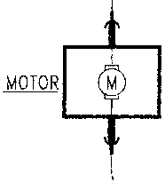
N.B. inverting the polarity (positive and earth) of an electric motor inverts its direction of rotation: therefore, particular attention must be paid that the two terminals are connected correctly, using for example a polarity detector.
NOTE: for these mechanisms it is possible for faults to be caused by mechanical and not electric problems. In this case the other groups of the manual should be consulted.
RHEOSTATS:
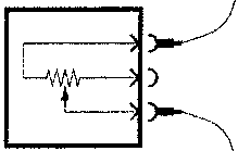
Rheostats are variable resistances: when voltage (12 V) is applied to the main terminals, the output signal from the third terminal is changed by a mechanical action (eg. rotating an adjustment washer....).
To check correct operation connect one prod of a multimeter set to measure ohms to one of the main terminals and the other to the third terminal: by acting on the adjustment washer for example, the resistance measured should change noticeably.
TERMOSTATS/PRESSURE SWITCHES:
These are instruments which emit a signal which is directly proportional to the temperature/pressure they measure. From a schematic electrical point of view they are rheostats of which the resistance varies with the readings taken.
To check these devices therefore, follow the indications given for rheostats using suitable equipment to enable the temperature or pressure to be changed.
ELECTRIC MOTORS/SOLENOIDS:
Electric motors and solenoids are mechanisms which are essentially composed of electrical windings and for this reason checking the operation of these components consists in verifying if electrical continuity has reached the windings or not; then proceed as mentioned above using the multimeter.
It is also possible to check a component when it is installed on the vehicle: disconnect it and check the operation (for instance the rotation of the motor) connecting the terminals to a 12 V power source.
EARTH POINTS:
An earth point is not correctly connected if oxidation is present, if it is not securely fastened to the body or if the cables reaching it are bared or damaged.
To check whether an earth point is really at "0 potential", connect it to the prod of a multimeter set to measure ohms; connecting the other prod to the battery negative pole the resistance reading should be = 0 Ω; if this is not the case, carefully inspect the earth as it is faulty.
SOLDERS:
Numerous solders between wires are present on the vehicle: they are carried out using the ultrasound technique which makes them extremely reliable and safe.
If it becomes necessary to check a solder, simply check the continuity between the different wires which converge on it: if this proves unsuccessful the solder cannot be repaired and the wiring must be replaced.
CONTROL UNITS AND ELECTRONIC DEVICES IN GENERAL:
Nowadays, electronic control units are the most important components of the car. Because of this reason, they are almost 100% reliable as their protection circuits have been designed especially for this purpose.
Because of their complexity, electronic control units require special diagnosis devices as the use of the multimeter is neither sufficient nor advisable.
Generally, the control units are provided with a special diagnosis socket for connection to the ALFA ROMEO TESTER.
Parts & tools for this job For 1995 Alfa Romeo GTV / Spider
- TOOLOBD2 scannerSearch: OBD2 scanner
- TOOLDigital multimeterSearch: automotive digital multimeter
- TOOLBack-probe test leadsSearch: back probe test leads
Links open Amazon search results in a new tab. As an Amazon Associate I earn from qualifying purchases.