
Wiring diagrams
- Make
- Alfa Romeo
- Model
- GTV / Spider GTV and Spider (916) Factory Service Manual
- Year
- 1995–2000
- Section
- 55-1 Introduction › Wiring diagrams
WIRING DIAGRAMS
The wiring diagrams are made following the operation of the circuit in order to make it easier to understand them, therefore quicker to identify a fault.
The lay-out follows the "flow" of the current and signals, starting from the power source (always placed higher up) passing the components and reaching the earths located lower down.
The power supply is represented schematically with different symbols which vary depending on the position of the key in the ignition:
- – line under constant supply (directly connected to the battery)
- – line supplied when the ignition key is turned to "RUN" (first position of the key)
- – line supplied when the key is turned to "STARTING" (second position of the key which is disengaged when the key is released)
- – line supplied when the key is either in the "RUN" or "STARTING" position.
- – line supplied when the key is in the "PARKING" position (key turned in the opposite direction and withdrawn after pressing the special button).
A special section ("Power Supply") deals in detail with the power supply to all the lines and operation of the ignition switch.
The fusebox is not represented wholly in the single diagrams and only the components useful to the diagram under examination are given; a complete description of the whole fusebox is given in the specific section ("Fusebox").
All the components and connectors are represented in the diagrams by an alphabetic code (eg. A10). The initial letter of this code represents the type of component:
- A STARTING - RECHARGING
- B MANUAL ELECTRICAL CONTROLS
- C INSTRUMENTATION
- D WARNING LIGHTS
- E EXTERIOR LIGHTS
- F INTERIOR LIGHTS
G FUSEBOXES - CONNECTORS - EARTHS
H SWITCHES
I RELAYS
L SENDERS
M ELECTROMAGNETS - SOLENOID VALVES
N ELECTRONIC DEVICES - INTERMITTENCES - TIMERS
O SERVICES
P ELECTRIC MOTORS
Q HEATING/VENTILATION - AIR CONDITIONING
R SAFETY DEVICES
S ELECTRONIC INJECTION
T DIAGNOSIS
A complete key is given at the end of all the wiring diagrams.
The names of the components are given in the charts and the codes are circled, but, for reasons of space, the codes for simple connectors (connections) are only underlined.
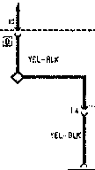
The components are always shown in their rest position: eg. the N.C. (normally closed) contacts are shown closed, the relays deactivated, etc..
The outline of a component is hatched to indicate that in the chart in question only part of it is shown; for example, the fusebox, due to the reasons mentioned above, will always be shown hatched.
Wherever necessary, arrows indicate references to other relevant diagrams.
Parts & tools for this job For 1995 Alfa Romeo GTV / Spider
- TOOLDigital multimeterSearch: automotive digital multimeter
- PARTAssorted fuse kitSearch: car fuse assortment kit
- TOOLWire crimper and connector kitSearch: wire crimper connector kit
Links open Amazon search results in a new tab. As an Amazon Associate I earn from qualifying purchases.