
Intake box
- Make
- Alfa Romeo
- Model
- GTV / Spider GTV and Spider (916) Factory Service Manual
- Year
- 1995–2000
- Section
- Air intake circuit › Intake box
Right-hand drive variantsIntake box · page 1 of 4
INTAKE BOX
REMOVAL/REFITTING
- Set the car on a lift.
- Disconnect the battery (-) terminal.
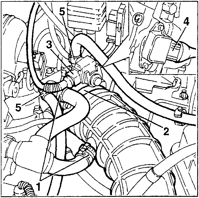
- Disconnect the oil vapour recirculation pipe from the throttle body and from the corrugated sleeve.
- Slacken the fastening clamp and disconnect the corrugated sleeve from the throttle body.
- Disconnect the electrical connection from the constant idle sped actuator.
- Disconnect the electrical connection from the throttle potentiometer.
- Disconnect the two engine coolant fluid inlet and outlet pipes from the throttle body.
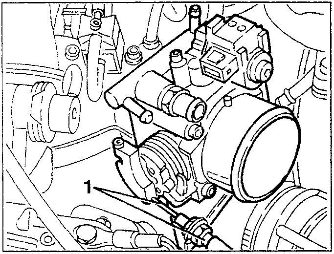
- Disconnect the accelerator cable from the throttle.
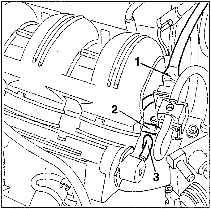
- Disconnect the electrical connection from the E.G.R. modulation solenoid valve.
- Disconnect the connection pipe to the E.G.R. valve from the modulation solenoid valve.
- Disconnect the fuel pressure regulator vacuum takeoff pipe.
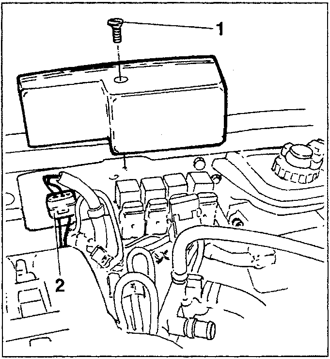
- Slacken the screw and remove the relay unit cover.
- Disconnect the lambda probe connection.
Parts & tools for this job For 1995 Alfa Romeo GTV / Spider
- TOOLDigital multimeterSearch: automotive digital multimeter
- PARTAssorted fuse kitSearch: car fuse assortment kit
- TOOLWire crimper and connector kitSearch: wire crimper connector kit
Links open Amazon search results in a new tab. As an Amazon Associate I earn from qualifying purchases.