
Intake manifold
- Make
- Alfa Romeo
- Model
- GTV / Spider GTV and Spider (916) Factory Service Manual
- Year
- 1995–2000
- Section
- Air supply system › Intake manifold
Variants – 3.0 V6 24VIntake manifold · page 1 of 3
INTAKE MANIFOLD
REMOVAL/REFITTING
- Disconnect the (-) battery terminal.
- Disconnect the front knock sensor electrical connection.
- Disconnect the intake manifold earth wire (front).
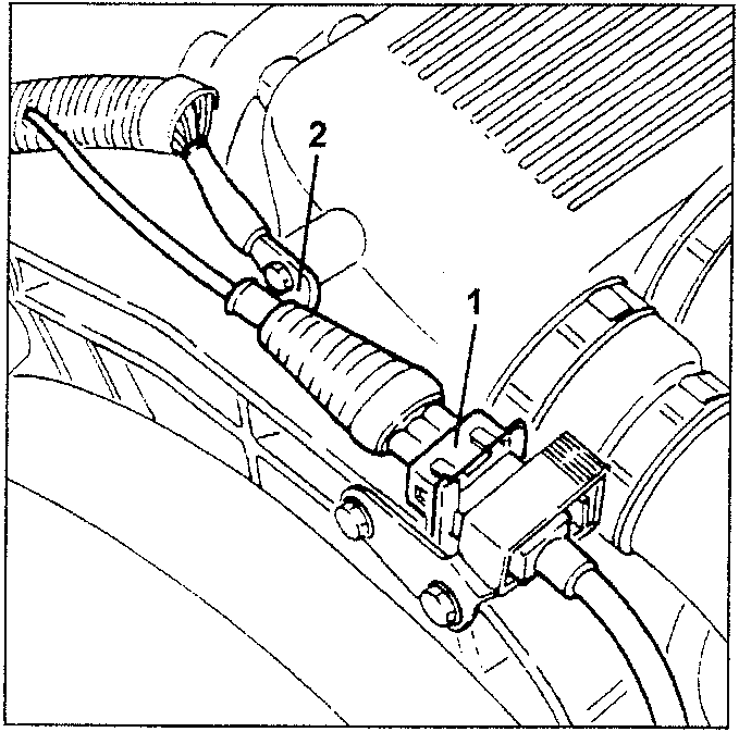
- Front knock sensor electrical connection
- Intake manifold earth wire (front)
- Disconnect the oil vapour recovery pipe from the separator.
- Disconnect the condensed oil recovery pipe from the separator.
- Disconnect the constant idling actuator electrical connection.
- Disconnect the fuel vapour recovery pipe from the intake manifold.
- Disconnect the brake booster vacuum pipe from the intake manifold.
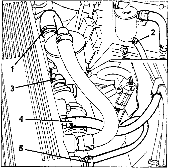
- Oil vapour recovery pipe
- Condensed oil recovery pipe
- Constant idling actuator electrical connection
- Fuel vapour recovery pipe
- Brake booster vacuum pipe
- Remove the plastic relay, fuse and electrical connection guard.
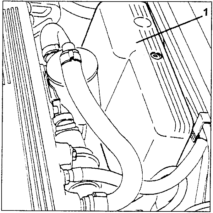
- Plastic relay, fuse and electrical connection guard
- Disconnect the constant idling actuator air intake pipe from the corrugated sleeve.
- Loosen the two fastening nuts and remove the EGR valve from the intake manifold.
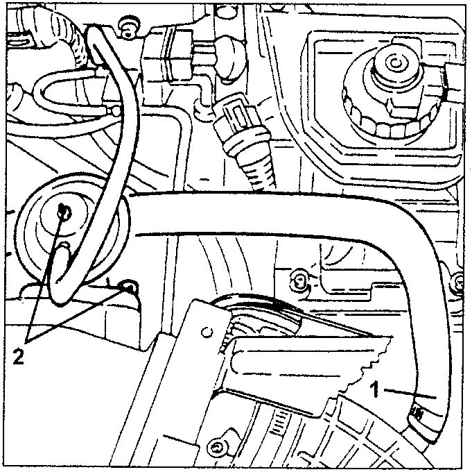
- Constant idling actuator air intake pipe
- EGR valve
Parts & tools for this job For 1995 Alfa Romeo GTV / Spider
- TOOLTorque wrenchSearch: 3/8 inch torque wrench
- TOOLSocket setSearch: socket set metric
- BOOKHaynes manualSearch: Haynes manual Alfa Romeo GTV / Spider
Links open Amazon search results in a new tab. As an Amazon Associate I earn from qualifying purchases.