
Blower Motors
- Make
- Aston Martin
- Model
- DB7 Factory Workshop Manual Volume 2: Electrics, Body and Air Conditioning
- Year
- 1994–1998
- Section
- Electronic control module and in-car controls › Blower Motors
Blower Motors
The air conditioning system has two blower motors (Fig. 1-7) that operate together to maintain the flow of air into the car at the desired level. The motors are supplied from an ignition switched supply through transistorised control circuits fitted in the motor outlets. The circuits steplessly vary the speed of the motors at 1 and 2 selections of the mode switch and operate the motors to high speed when 3 is selected. The electronic components are assembled on a heat sink and include a power transistor (Fig. 1-9) and feedback diode (Fig. 1-8). The switches are supplied and controlled by the ECM.
When the mode switch is set to 3, the high speed relay (Fig. 1-10) is energised from pin 16 of the ECM, opening a path to earth-ground, and allowing full battery voltage to be applied to the motor. At 1 and 2, the motor is supplied with a continuously variable voltage by the power transistor and the earth-ground return is made via the ECM. The feedback diode enables the ECM to sense the voltage at the negative terminal of the blower motor.
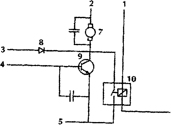
- Output signal from Pin 16 ECM
- Power feed
- Blower feedback
- Blower output Left Pin 31, Right 32
- Control switch earth-ground
- ECM earth-ground Pin 45
- Blower motor
- Feedback diode
- Power transistor
- High speed relay
Potentiometers
Lower Feedback Potentiometer
The lower feedback potentiometer determines the position of the lower blend flap in the air conditioning unit and feeds this information to the ECM. The ECM is thereby able to command the lower flap servo motor to move the flap to a new position and maintain the temperature of the air to the feet and rear outlets at the desired level.
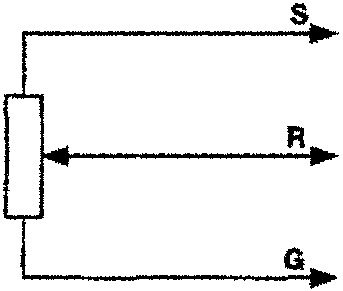
- +5 volts from ECM Pin 43
- Feedback signal to ECM Pin 29
- Earth-Ground
The potentiometer is supplied with +5V from pin 43 of the ECM and returns its feedback signal via pin 29. The feedback signal is 100mV (COLD AIR) to 1.2V (HOT AIR). The potentiometer also provides a single feedback signal of 2.9V when the blend flap is in DEFROST. In this position, the feet and rear outlets are closed and all air is directed to the screen.
Parts & tools for this job For 1994 Aston Martin DB7
- TOOLA/C manifold gauge setSearch: AC manifold gauge set
- TOOLUV leak detection kitSearch: AC UV leak detection kit
- PARTCabin filterSearch: Aston Martin DB7 1994 cabin filter
Links open Amazon search results in a new tab. As an Amazon Associate I earn from qualifying purchases.