
Engine (03.00)
- Make
- Aston Martin
- Model
- DB9 Factory Workshop Manual
- Year
- Issue 2, 2005
- Section
- Ignition System › Engine (03.00)
Engine (03.00)
Ignition System (03.07)
Description
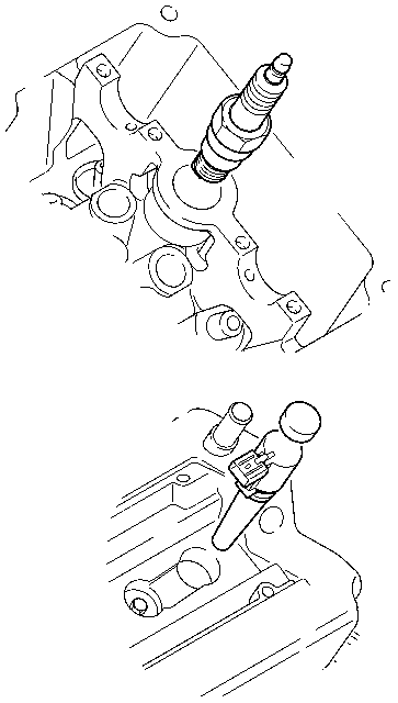
The ignition system consists of an ignition coil for each individual cylinder located on each individual spark plug.
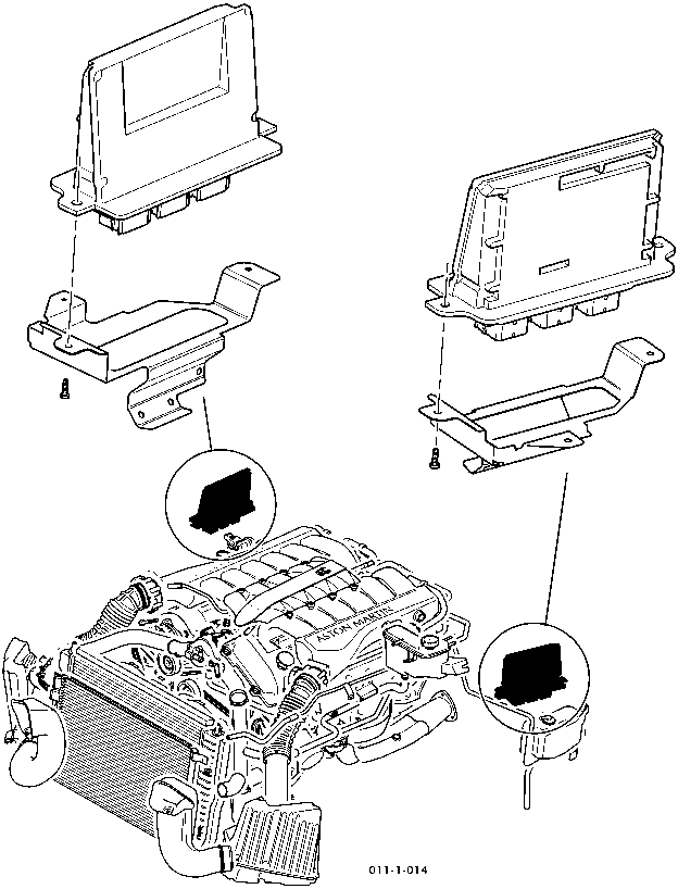
There are two crankshaft sensors located on the front of the engine - only the RH sensor is used. The second crankshaft sensor is located on the flywheel housing (LH side).
An alternating voltage signal from two Crankshaft Position Sensors (CPS) is converted by the Powertrain Control modules (PCMs). This digital signal is then used to position the 'On' and 'Off' time of the primary circuit of the ignition coil. The effective range for ignition timing control is increased by the fact that there are no rotating parts. On the basis of engine speed and load inputs, the PCMs determine the ignition timing. This function also takes other inputs into consideration such as engine temperature, throttle position and transmission control module (TCM) inputs.
- In the event of a short circuit to ground between the fusebox and the coil or the coil and the PCM the fuse would blow and all ignition coils on that bank would cease to function.
- If an ignition coil 'short circuits' internally the ignition coil will fail instead of its fuse. This allows the remaining ignition coils to continue functioning.
- In the event of a wiring harness failure between the PCM an7d the ignition coil, the ignition coil will fail instead of its fuse. This allows the remaining ignition coils to continue functioning.
The twelve spark plugs are fired in sequence by the two PCMs. Ignition timing can vary from 55° before TDC to 10° after TDC.
Crank position sensors
Specifications
| Spark Plugs | |
|---|---|
| Firing order | 1 - 7 - 5 - 11 - 3 - 9 - 6 - 12 - 2 - 8 - 4 - 10. |
| Type | Dual Platinum Fine Wire |
| Gap | 1.2 - 1.3 mm |
| Torque | 16-20 Nm |
| Camshaft Sensors | |
|---|---|
| Air Gap | 1 ±0.5 mm |
| Torque Figures | ||
|---|---|---|
| Description | Nm | lb./ft. |
| Spark plugs | 16-20 | 12-15 |
| Ignition coils | 5-7 | 4-5.5 |
| Spark plug cover | 2.5-3.5 | 2-3 |
Parts & tools for this job For 2005 Aston Martin DB9
- PARTEngine gasket setSearch: Aston Martin DB9 2005 engine gasket set
- TOOLTorque wrenchSearch: 3/8 inch torque wrench
- TOOLFeeler gauge setSearch: feeler gauge set
Links open Amazon search results in a new tab. As an Amazon Associate I earn from qualifying purchases.