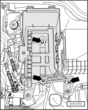
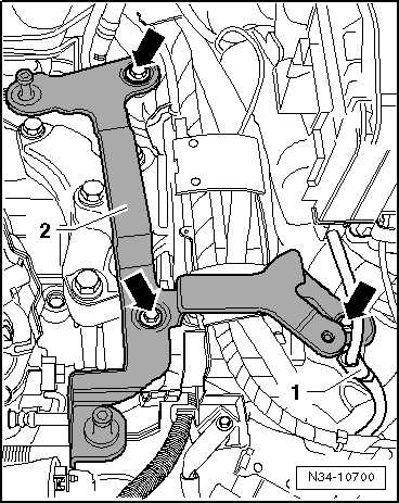
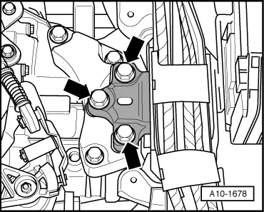
audi Workshop Repair Guides

Audi Workshop Service and Repair Manuals

Removing and installing pendulum support > < Exploded view - assembly mountings
Removing and installing gearbox mounting
Special tools and workshop equipment required
   
t  Support bracket -10 - 222 A-
  W00-0225
t  Removal lever -80 - 200- for vehicles from 06.2008 onwards
  W00-0353
t  Transportation shackle -2024 A /2- for vehicles with TFSI engine (with timing chain)
  W00-0224
Removing
Vehicles from 06.2008 onwards:
–  Lever clip off sealing element using removal lever -80 - 200- and fold up sealing element.
  A10-11130
Vehicles with TFSI engine (with timing chain):
–  Remove air cleaner housing completely → Rep. Gr.24.
–  Remove engine cover panel → Rep. Gr.10.
  A10-10760
  Caution
When disconnecting the battery there is a risk of serious damage to electronic components:
Observe the correct procedure for disconnecting the battery.
–  Remove battery → Electrical system; Rep. Gr.27.
–  Remove battery tray -arrows- (detach front of battery tray from air duct if applicable).
  A10-1572
–  Bolt transportation shackle -2024 A /2- to engine lifting eye using flange nut -arrow-.
  A10-10768
–  Set up support bracket -10 - 222 A- on wing mounting flanges. Spindles face to the front.
–  Hook spindles -10 - 222 A /11- onto transportation shackle -2024 A /2- and engine lifting eye.
–  Take up weight of engine/gearbox assembly evenly with both spindles; do not lift.
  A10-1645
Vehicles with TFSI engine (with toothed belt):
–  Completely remove engine cover panel and air cleaner (top section) → Rep. Gr.24.
  A10-10249
  Caution
When disconnecting the battery there is a risk of serious damage to electronic components:
Observe the correct procedure for disconnecting the battery.
–  Remove battery → Electrical system; Rep. Gr.27.
–  Remove battery tray -arrows- (detach front of battery tray from air duct if applicable).
  A10-1572
–  Set up support bracket -10 - 222 A- on wing mounting flanges. Spindles face to the front.
–  Hook spindles -10 - 222 A /11- onto engine lifting eyes.
–  Take up weight of engine/gearbox assembly evenly with both spindles; do not lift.
  A10-1645
Vehicles with V6 engine:
–  Remove air cleaner housing completely → Rep. Gr.24.
  A10-1879
–  Detach line -1- from air cleaner bracket -2-.
  N34-10700
  Caution
When disconnecting the battery there is a risk of serious damage to electronic components:
Observe the correct procedure for disconnecting the battery.
–  Remove battery → Electrical system; Rep. Gr.27.
–  Remove battery tray -arrows- (detach front of battery tray from air duct if applicable).
  A10-1572
–  Fix a shackle -10-222 A/12- to engine lifting eye (rear right).
–  Position support bracket -10 - 222 A- on wing mounting flanges with adapters -10 - 222 A /3-.
–  Hook spindles -10 - 222 A /11- onto shackle -10-222 A/12- and engine lifting eye.
–  Take up weight of engine/gearbox assembly evenly with both spindles; do not lift.
  A10-1897
Vehicles with TDI engine:
–  Remove air cleaner housing completely → Rep. Gr.23.
–  Remove engine cover panel → Rep. Gr.10.
  A10-1667
–  Position support bracket -10 - 222 A- on wing mounting flanges with adapters -10 - 222 A /3-.
–  Hook spindles -10 - 222 A /11- onto engine lifting eyes.
–  Take up weight of engine/gearbox assembly evenly with both spindles; do not lift.
  A10-1686
Continued for all vehicles:
–  Remove bolts -arrows-.
  A10-1678
–  Open retainers for wiring duct -arrows-.
–  Cut open cable tie -1- and push electrical wiring to one side.
–  Unclip wiring duct.
  A10-10563
–  Remove bolts -1- and detach gearbox mounting -A-.
Installing
l  Tightening torques → Chapter „Exploded view - assembly mountings“
Installation is carried out in reverse sequence; note the following:
–  Secure gearbox mounting -A- to longitudinal member.
  A37-0685
  Caution
The threads in the gearbox support can be damaged if the bolts are not inserted straight.
t  
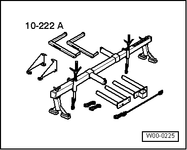
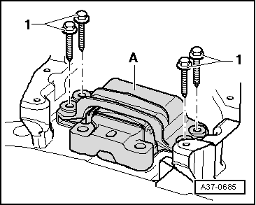
Before fitting the bolts -arrows-, the gearbox support and the support arm of the gearbox mounting must be aligned absolutely parallel. If necessary, push the gearbox up at the rear with a trolley jack.
t  
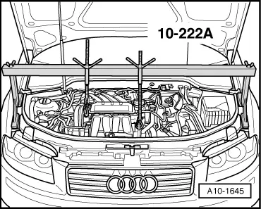
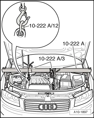
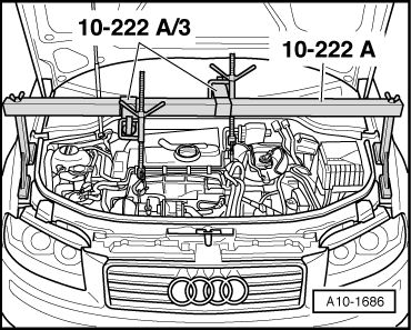
Do not remove support bracket -10 - 222 A- until all bolts -arrows- securing the engine/gearbox mountings have been tightened to the specified torque.
–  Pull gearbox up with spindle on support bracket until gearbox support contacts support arm of gearbox mounting.
–  Bolt support arm of gearbox mounting onto gearbox support using new bolts -arrows-.
–  Adjust assembly mountings → Rep. Gr.10.
–  Detach support bracket -10 - 222 A- from engine.
–  Install battery tray and battery → Electrical system; Rep. Gr.27.
–  Install air cleaner housing → Rep. Gr.23 or → Rep. Gr.24.
  A10-1678

Removing and installing pendulum support > < Exploded view - assembly mountings