
Catera V6-3.0L VIN R (1997)
Important: Ensure the rear differential stays adequately supported. Ensure that the method of support will not be disrupted by partial lowering of
the rear axle cradle.
25. Support the rear lower control arm.
26. Remove the underbody heat shield nuts.
27. Remove the underbody heat shields.
28
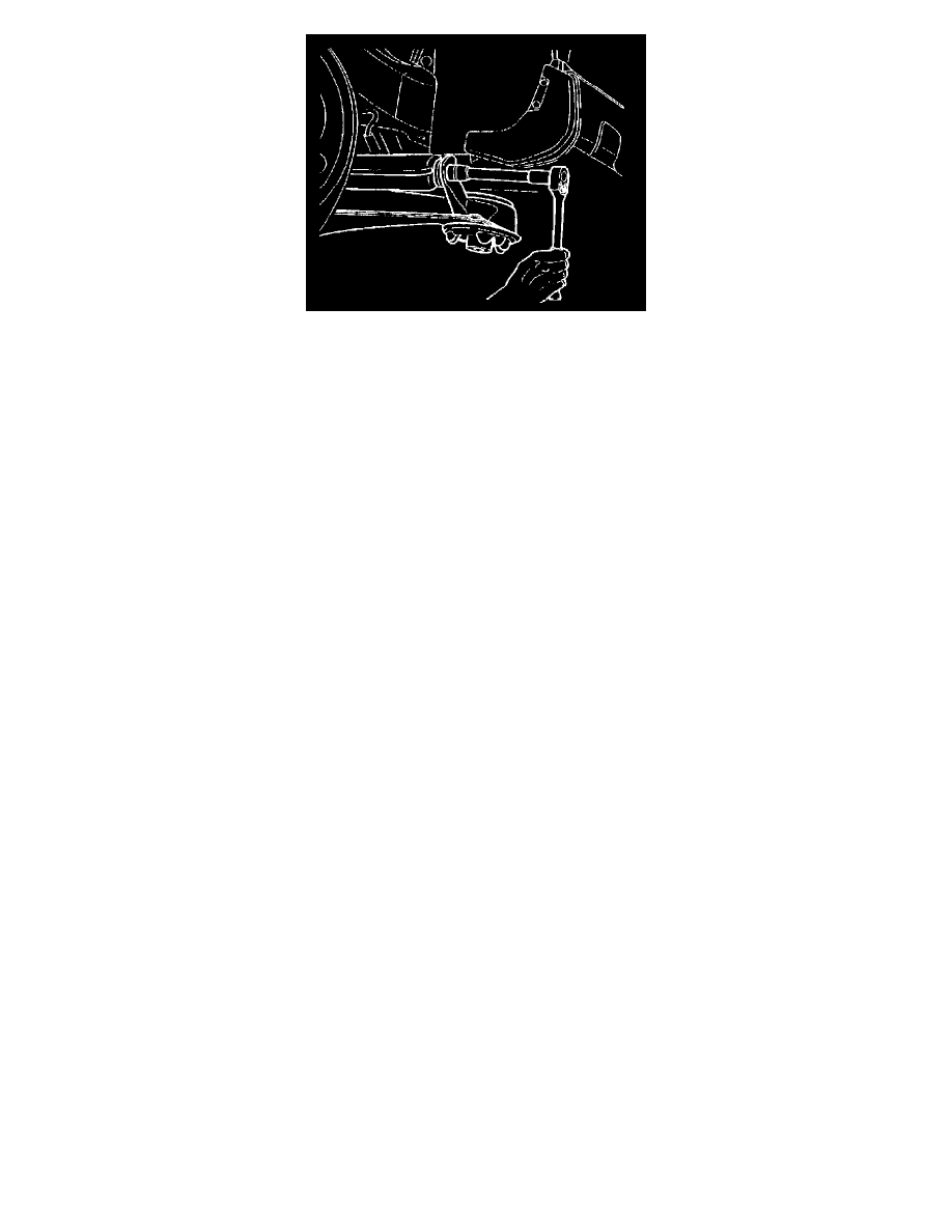
Remove the propeller shaft center bearing bracket bolts.
29. Remove the rear support flange bolts.
30. Remove the rear support bushing bolt.
31. Lower the control arm to allow access to the outboard lower control arm bolt.
32. Remove the inboard lower control arm bolt.
33. Remove the outboard lower control arm bolt.
34. Remove the rear axle lower control arm.
INSTALLATION PROCEDURE
1. Install the rear axle lower control arm.
NOTICE: Use the correct fastener in the correct location. Replacement fasteners must be the correct part number for that application. Fasteners
requiring replacement or fasteners requiring the use of thread locking compound or sealant are identified in the service procedure. Do not use
paints, lubricants, or corrosion inhibitors on fasteners or fastener joint surfaces unless specified. These coatings affect fastener torque and joint
clamping force and may damage the fastener. Use the correct tightening sequence and specifications when installing fasteners in order to avoid
damage to parts and systems.
^
Install the inboard rear lower control arm bolt and install the outboard rear lower control arm bolt.
^
Tighten the rear axle lower control arm bolts to 100 Nm (74 ft. lbs.).
2. Raise the rear lower control arm into position to allow for support bushing and to allow for flange bolt alignment.
3. Install the rear axle support bushing bolt to a loose position.
4. Install the rear support flange bolts to a loose position.
a. Tighten the rear axle support bushing bolt to 125 Nm (92 ft. lbs.).
b. Tighten the rear support flange bolts to 65 Nm (48 ft. lbs.).
5. Remove the support from the rear lower control arm.
6. Position the rear cradle to enable the propeller shaft center bearing bracket installation.
7. Install the propeller shaft center bearing bracket bolts.
^
Tighten the propeller shaft center bearing bracket bolts to 20 Nm (15 ft. lbs.).
8. Install the underbody heat shields.
9. Install the underbody heat shield nuts.
^
Tighten the underbody heat shield nuts to 2 Nm (18 inch lbs.).
10. Install the rear spring.
11. Raise the rear axle cradle into position.
12. Align the cradle mounts to the reference marks previously scribed during the removal procedure.
13. Install the rear axle cradle mount to the vehicle body bolts.
^
Tighten the rear axle cradle mount to the vehicle body bolts to 65 Nm (48 ft. lbs.).
14. Remove the support fixture from the rear differential.
15. Support the rear lower control arm to allow for shock absorber lower mount bolt installation.
16. Install the shock absorber lower mount bolt.
^
Tighten the shock absorber lower mount bolt to 110 Nm (81 ft. lbs.).
17. Remove the rear lower control arm support.
18. Install the stabilizer shaft link connection at the rear axle lower control arm. Refer to Stabilizer Shaft Link Replacement
19. Install the rear outer tie rod to the rear axle control arm.