
Introduction - clutch
- Make
- Fiat
- Model
- Bravo Factory Service Manual
- Year
- 2007–2014
- Section
- General › Introduction - clutch
INTRODUCTION - CLUTCH
CONSTRUCTION SPECIFICATIONS
The clutch is single dry plate type, with flexible spring coupling and thrust release. The clutch release is implemented by a co-axial hydraulically operated device known as the "CSC system".
On all versions, friction materials free from non-environmentally friendly components have been adopted; special care has been taken in the development of new materials and the clutch assembly, with a view to guaranteeing excellent performance in terms of modulation and driving comfort with a consequent reduction in weight compared with traditional hydraulic operation. In particular the clutch pump has undergone a considerable improvement compared with the components usually adopted.
CLUTCH HYDRAULIC SYSTEM
The co-axial, hydraulically operated clutch release system is known as the "CSC system". This type of operation, which integrates the hydraulic actuator with the thrust bearing, makes it possible to maintain the performance of the system during the working life of the clutch and contributes to the reduction in noise and vibrations transmitted by the pedal.
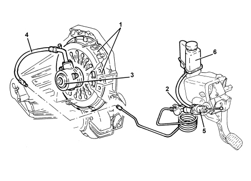
1. Clutch mechanism
2. Vibration damper
3. CSC actuator
4. Pipe connecting pump and actuator
5. Clutch pump
6. Brake-clutch fluid reservoir
Csc system
The CSC system is known as co-axial because the release actuator consists of an aluminium ring cylinder, fitted inside the clutch bell housing, positioned between the gearbox and the clutch mechanisms, co-axially in relation to the main shaft.
The advantage of the CSC system compared with conventional systems lies in the absence of kinematic couplings and friction resulting in improved reliability and functionality, making it easy to maintain.
The system features the following characteristics:
- constant adjustment of the clutch pedal height;
- constant force applied to the pedal over a period of time;
- elimination of any difficulties with the clutch pedal return;
- reduction of noise and vibrations transmitted to the pedal through the action of a vibration damper positioned in the cylinder oil pipe.
The pipe is connected to the actuator by means of a quick coupling with a built-in bleed valve.
The absence of a transmission crank mechanism found in traditional systems, the adoption of a clutch pump with plastic casing and piston and the use of plastic in the construction of the pedal unit has also allowed for a notable reduction in noise and in the overall weight of the system.
CSC HYDRAULIC ACTUATOR CYLINDER
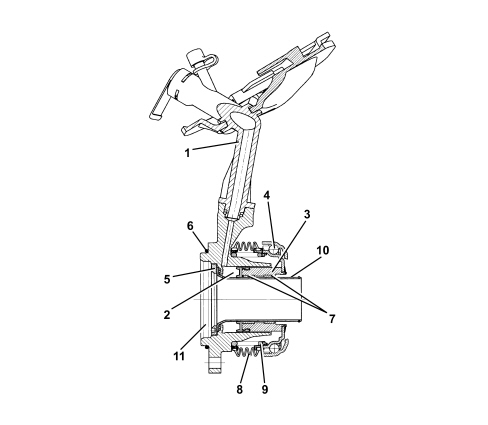
1. Oil intake pipe
2. Expansion chamber
3. Piston
4. Thrust bearing
5. Threaded closing flange
6. O-ring
7. Anti-wear pads
8. Rubber gaiter
9. Spring
10. Guide pipe
11. Oil seal housing
The clutch release takes place through the action of the clutch pump which sends oil, under pressure, via the pipe (1), into the expansion chamber (2).
The pressure of the oil causes the movement of the piston (3) which slides in the guide pipe (10) through the plastic anti-wear pads (7).
The piston is integrated with the thrust bearing (4), which presses on the pressure springs, thereby releasing the clutch.
As the pressure of the oil ceases, the actuator returns to the rest position by means of the thrust from the pressure springs.
The seal against any gearbox oil leaks that could emanate from inside the clutch bell housing is guaranteed by an oil seal and an O-ring (6).
There is a rubber gaiter (8), kept in position by a spring (9), as protection against the entry of any foreign bodies.
Clutch release pump
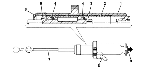
1. Case
2. Steel cylinder
3. Piston
4. Gasket
5. Piston detent fork
6. Protective gaiter
7. Operating rod
8. Oil inlet
9. Oil supply to CSC actuator
The clutch release pump has been designed with a plastic piston and casing to reduce the weight and with the operating shaft secured (T interface) to the piston. There is a steel cylinder, inside the casing in the area where the piston seals slide, to prevent the wear and distortions which result from the pressure.
The piston is prevented from coming out by a V-shaped piston detent fork, while a protective gaiter prevents the accumulation of dirt inside the cylinder.
The piston upper and lower end stops in the pump casing also determine the upper and lower end positions of the pedal.
CONSTRUCTION SPECIFICATIONS
The clutch is single dry plate type, with a thrust bearing in permanent contact with the pressure spring.
The driven plate is driven by pressure exercised by a diaphragm spring. Clutch release takes place via the hydraulic system operated by the pedal.
On all versions friction materials free from non-environmentally friendly components have been adopted; special care has been taken in the development of new materials and the clutch assembly, with a view to guaranteeing excellent performance in terms of modulation and driving comfort with a consequent reduction in weight compared with traditional hydraulic operation. In particular, the clutch pump has undergone a considerable improvement compared with the components usually adopted. It is equipped with:
- plastic casing, which further contributes to the reduction in weight;
- steel cylinder;
- plastic material piston.
The materials for the piston and the rubber seals have been developed specifically to operate with long strokes; in addition, the seal created by the contact between rubber and steel is excellent compared with conventional clutch pumps where the seal is created between rubber and cast iron.
COMPOSITION
The system consists of:
- a clutch pump (master cylinder) (2) which is fastened to the pedal unit and compresses the oil;
- a pipe (3) connecting the pump and the clutch operating cylinder;
- a clutch operating cylinder (4) fastened to the gearbox;
- linkage (5) operating the thrust bearing;
- a thrust bearing (6);
- a clutch drip tray with diaphragm pressure springs (7);
- a clutch plate (8);
- a fluid reservoir (1) shared with the braking system.
- vibration damper (9)
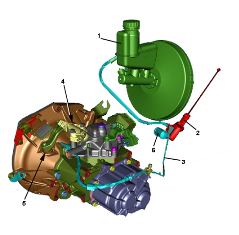
1. Brake/clutch fluid reservoir
2. Clutch pump
3. Pipe connecting pump and cylinder
4. Clutch operating cylinder
5. Linkage
6. Thrust bearing
7. Diaphragm spring
8. Clutch plate
9. Vibration damper
OPERATION
The pump (2), operated by the clutch pedal, pressurises the hydraulic circuit and operates the clutch control cylinder (4).
The latter acts on the linkage (5) which "pulls" the thrust bearing (3), overcoming the action of the pressure springs (7).
This action causes the release of the clutch plate (8) from the flywheel.
When the pedal is released, the action of the diaphragm springs (7) returns the mechanism to the original position.
CLUTCH RELEASE PUMP
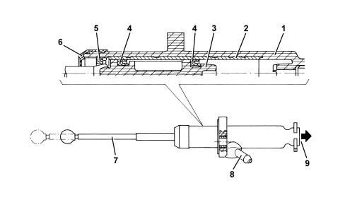
1. Case
2. Steel cylinder
3. Piston
4. Sealing gasket
5. Piston detent fork
6. Protective gaiter
7. Operating shaft
8. Oil inlet
9. Oil input to CSC actuator
The clutch release pump has been designed with a plastic piston and casing in order to reduce the weight, and with the operating shaft secured (T interface) to the piston. There is a steel cylinder, inside the casing in the area where the piston seals slide, to prevent the wear and distortions which result from the pressure.
The piston is prevented from coming out by a V-shaped piston detent fork, and a protective gaiter prevents the accumulation of dirt inside the cylinder.
The piston upper and lower end stops in the pump casing also determine the upper and lower end positions of the pedal.
Parts & tools for this job For 2007 Fiat Bravo
- PARTClutch kitSearch: Fiat Bravo 2007 clutch kit
- TOOLClutch alignment toolSearch: clutch alignment tool
- FLUIDGear oilSearch: Fiat Bravo manual gearbox oil
Links open Amazon search results in a new tab. As an Amazon Associate I earn from qualifying purchases.