
Anti-lock braking system
- Make
- Fiat
- Model
- Bravo /Brava (182) Factory Service Manual
- Year
- 1995–2001
- Section
- Anti-lock braking system › Anti-lock braking system
33 Braking systemAnti-lock braking system · page 1 of 2
Anti-lock braking system
REMOVING-REFITTING COMPONENTS OF THE ANTI-LOCK BRAKING SYSTEM
Electrohydraulic control unit
To remove the electrohydraulic unit, proceed as follows:
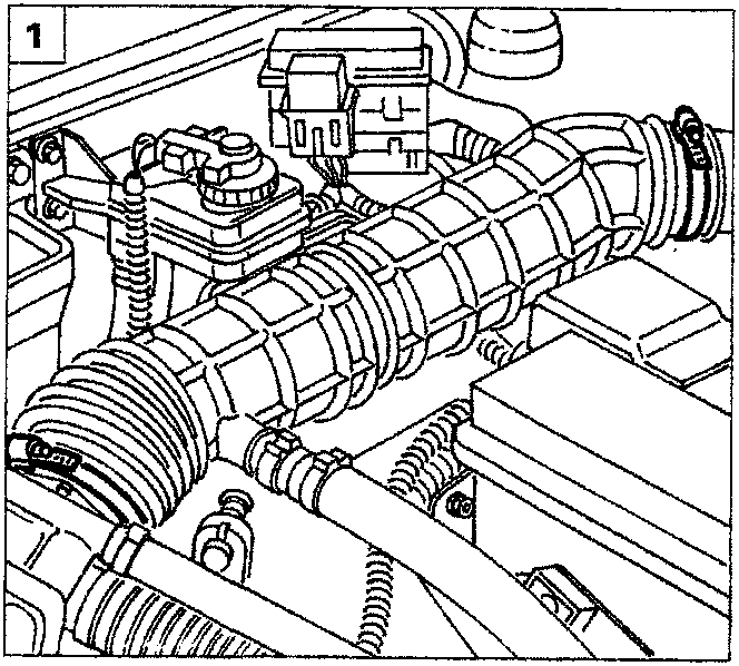
- undo the clips securing the inlet pipe;
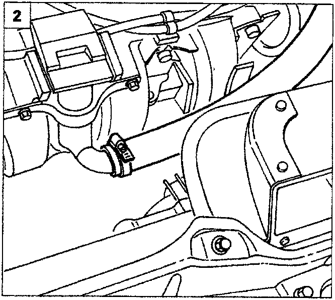
- undo the clip securing the oil vapour recirculation pipe and remove the complete inlet pipe;
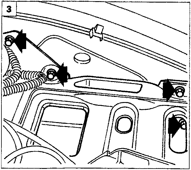
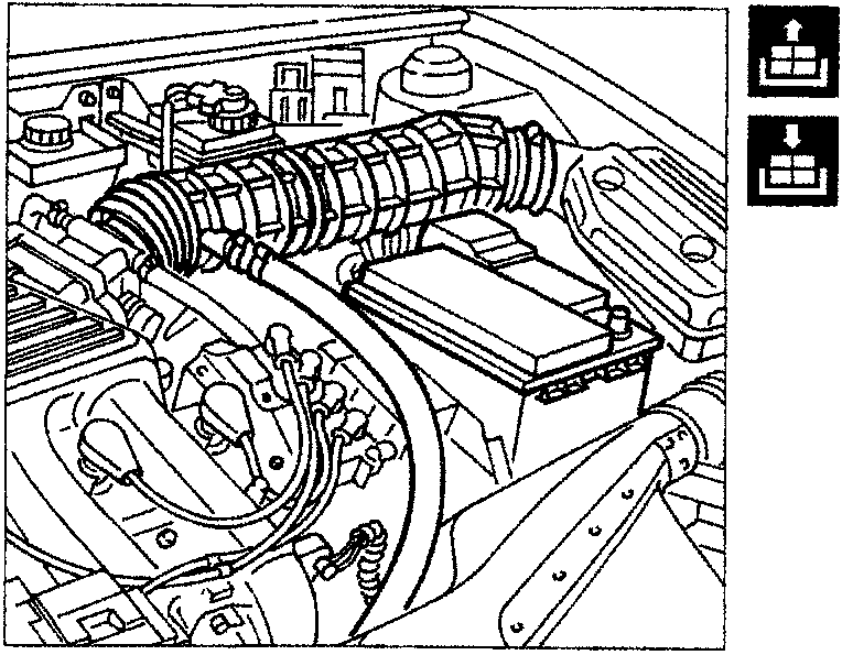
- remove the battery then undo the bolts indicated and move aside the battery cage;
Parts & tools for this job For 1995 Fiat Bravo
- TOOLTorque wrenchSearch: 3/8 inch torque wrench
- TOOLSocket setSearch: socket set metric
- BOOKHaynes manualSearch: Haynes manual Fiat Bravo
Links open Amazon search results in a new tab. As an Amazon Associate I earn from qualifying purchases.