
Wheel anti-lock system
- Make
- Fiat
- Model
- Bravo /Brava (182) Factory Service Manual
- Year
- 1995–2001
- Section
- Anti-lock braking system › Wheel anti-lock system
33 Braking systemWheel anti-lock system
Wheel anti-lock system
TEVES MK20 A.B.S. SYSTEM ELECTRICAL DIAGRAM
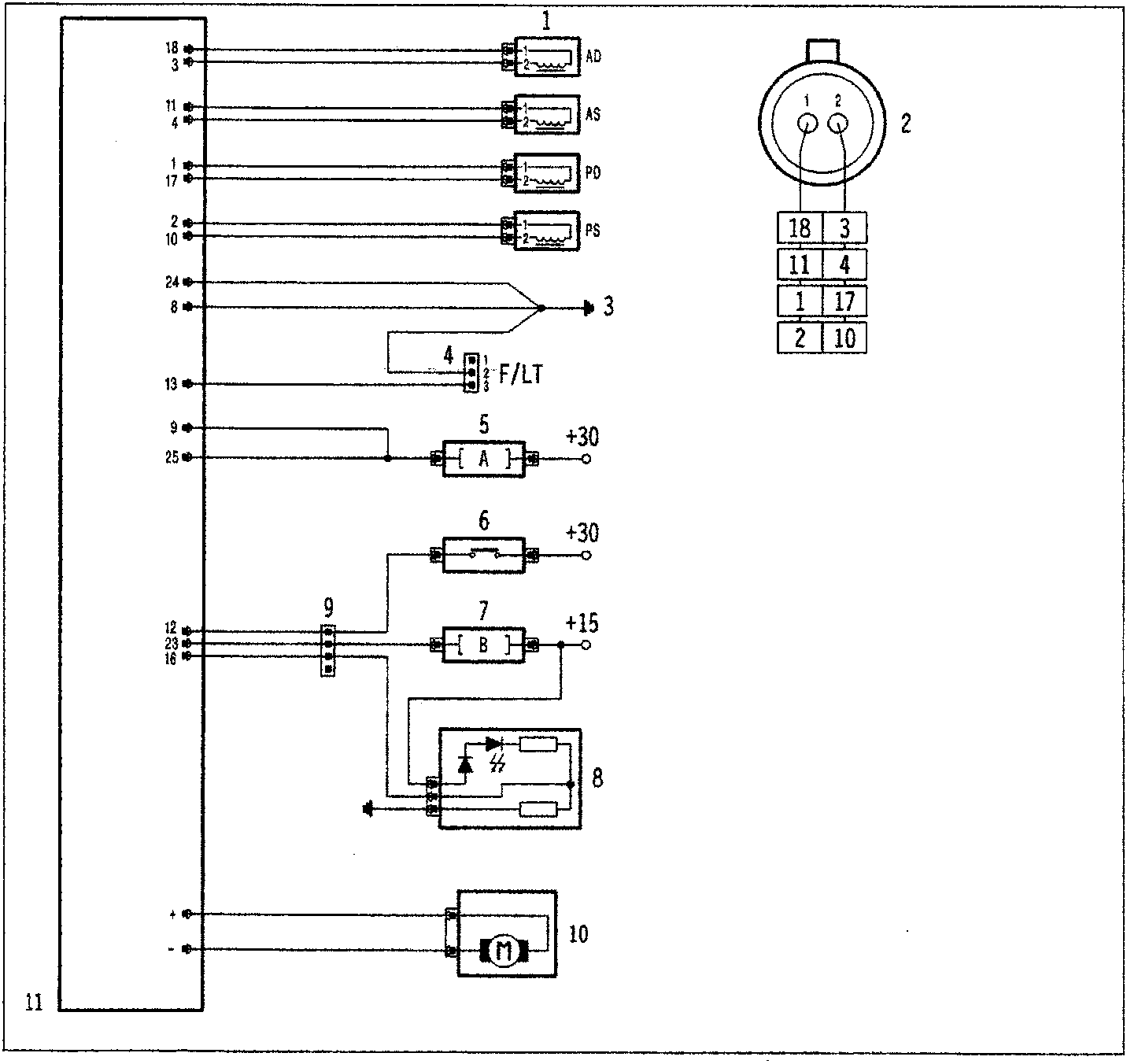
- Wheel speed sensors
- Wheel speed sensor connector (viewed from insertion side)
- Control unit ground
- F/L Tester diagnosis socket
- Fuse A (60A)
- Brake pedal switch
- Fuse B (10A)
- Instrument panel with failure warning lamp
- Connector interconnecting ABS wiring and dashboard
- Pump motor
- Control unit
NOTE The numbers printed inside boxes refer to the control unit pins.
Parts & tools for this job For 1995 Fiat Bravo
- TOOLTorque wrenchSearch: 3/8 inch torque wrench
- TOOLSocket setSearch: socket set metric
- BOOKHaynes manualSearch: Haynes manual Fiat Bravo
Links open Amazon search results in a new tab. As an Amazon Associate I earn from qualifying purchases.